Home »
Digital Electronics
The JK Flip Flop in Digital Electronics
In this tutorial, we will learn about the JK Flip Flop, the construction and working of the JK flip flop, and its applications in digital electronics.
By Saurabh Gupta Last updated : May 11, 2023
What is JK Flip Flop?
As we have already discussed the working of SR Flip Flop, we already know that, when both the inputs S (Set) and R (Reset) of the flip flop are provided with high input signal i.e., 1 then the output obtained in Q and Q remains the same, which is contradictory and not possible and thus results in an invalid state. So, we use JK flip flops to overcome this problem of SR flip flop.
Construction of JK Flip Flop
JK flip flop is nothing but an updated/modified version of SR flip flop in which certain modifications are made to avoid the invalid state which occurred in SR flip flop. The circuit diagram of a JK Flip Flop made using NAND Gates is shown as:
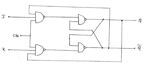
It consists of two inputs J and K which correspond to the same inputs as in the case of SR flip flop. The input J corresponds to S (Set) and the input K corresponds to R (Reset). The change that can be observed in the circuit diagram of the JK flip flop is the outputs of the latch are connected to its own loading gate, which helps in getting the complemented outputs when both J and K are supplied with high inputs i.e., 1.
Positive Edge Triggered JK Flip Flop
We often encounter the problem of toggling in the working of JK flip flop. To avoid this toggling, we make use of an edge-triggered flip flop.
The logic symbol and truth table of a positive edge-triggered JK flip flop is shown below:
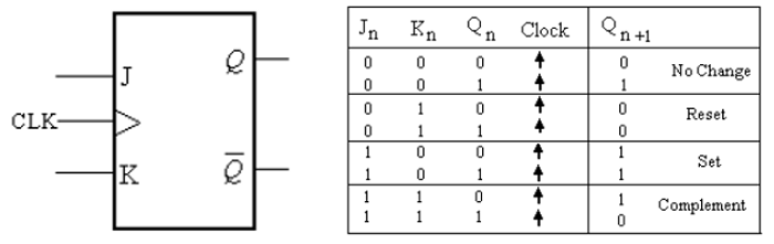
The arrows pointing upwards in the truth table shows that the transitions at outputs of the flip-flop will occur at the leading edge of the clock pulse.
Case 1: When J=0 and K=0, no change in state takes place in the output.
Case 2: When J=0 and K=1, the flip flop resets itself on the positive edge of the clock pulse.
Case 3: When J=1 and K=0, the flip flop sets itself on the positive edge of the clock pulse.
Case 4: When J=1 and K=1, the flip flop is in the toggling state and goes to the opposite state at the positive edge of the clock pulse.
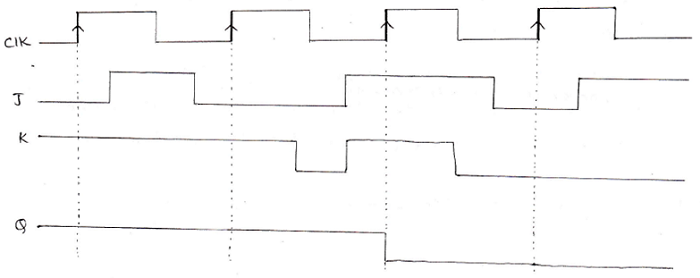
Input and Output waveform of a positive edge-triggered JK Flip Flop:
Characteristic Table and Characteristic Equation of a JK Flip Flop
From the above truth table of the JK flip-flop, we can derive a characteristic table based upon inputs given to J and K and the output obtained in the next state (Qn+1), which in result can help us to derive a characteristic equation for JK flip flop. The characteristic table for JK flip-flop is given as:
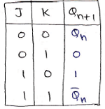
The characteristic equation of JK Flip - Flop can be derived using K-Map as:
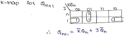
The characteristic equation is given below,
Qn+1 = K.Qn + J.Qn