Home »
Digital Electronics
Programmable Logic Devices in Digital Electronics
In this tutorial, we will learn about the different types of programmable logic devices, their types, and sub-types, then we will learn about the PROM.
By Saurabh Gupta Last updated : May 11, 2023
Logic devices can be broadly categorized as:
- Fixed Logic Devices (FLDs)
- Programmable Logic Devices (PLDs)
Fixed Logic Devices (FLDs): As the name indicates, the circuits in the FLD are permanent, they perform one function or set of functions. Once manufactured, they cannot be erased.
In this tutorial, we will learn about the Programmable Logic Devices (PLDs).
What are Programmable Logic Devices (PLDs)?
Programmable Logic Device (PLD) is an IC that contains large number of gates, Flip-flops, and registers that are inter-connected on the chip. Programmable Logic Devices (PLDs) can be reconfigured to perform any number of functions at any time.
Types of Programmable Logic Devices (PLDs)
1. Simple PLDs/ sequential PLDs
- PROM (Programmable Read-Only Memory)
- PLA (Programmable Logic Array)
- PAL (Programmable Array Logic)
2. Complex PLDs (CPLDs)
- Field Programmable Gate Arrays (FPGA)
-
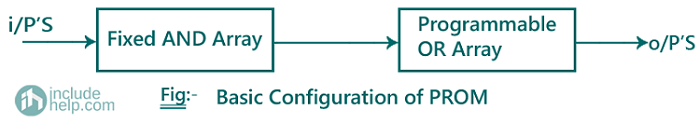
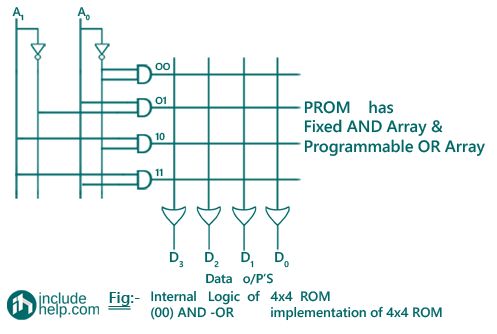
Programmable Read Only Memory (PROM)
Note: In case of arrays logic symbol for OR gate is given as:

The conventional logic symbol for OR gate is given as:

Programmable Logic Devices Examples
Example 1
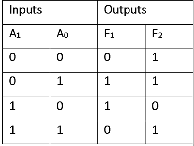
Implement the following Boolean functions using PROM.
F1(A1, A0) = ∑ m(1,2), F2(A1, A0) = ∑ m(0,1,3)
Solution
Input variables are A1, A0 (2 variables). Therefore, we use a 2:4 decoder.
F1(A1, A0) = ∑ m(1,2) = A1A0 + A1A0
F2(A1, A0) = ∑ m(0,1,3) = A1A0+ A1A0 + A1A0
Truth Table
Logic Diagram
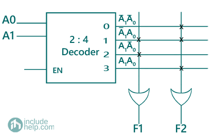
Fig. Implementation of F1, F2 using PROM
Example 2
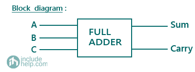
Implement Full Adder using PROM.
Solution
Block Diagram of a Full Adder can be represented as:
The truth table of a full adder is represented as:
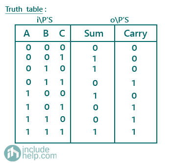
Therefore, expression for sum is given as: Sum = ∑ m (1,2,4,7)
and expression for carry is given as: Carry = ∑ m (3,5,6,7)
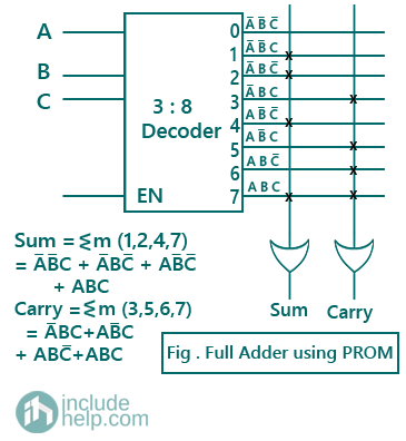
Logic Diagram: There are three input variables = A, B, C, therefore we will be using a 3:8 decoder.
Example 3
Design a combinational circuit using PROM, in which a 3-bit binary number is provided as input and the circuit generates its equivalent Excess-3 code.
Solution
The truth table for generating excess-3 codes for corresponding 3-bit binary number is given as:
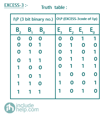
Therefore, E0 (B2, B1, B0) = ∑ m (0,2,4,6)
E1 (B2, B1, B0) = ∑ m (0,3,4,7)
E2 (B2, B1, B0) = ∑ m (1,2,3,4)
E3 (B2, B1, B0) = ∑ m (5,6,7)
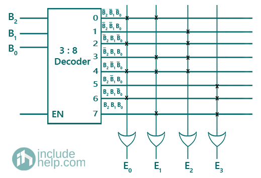
Logic Diagram: Since, there are three input variables = B2, B1, B0, therefore we will be using a 3:8 decoder.
Example 4
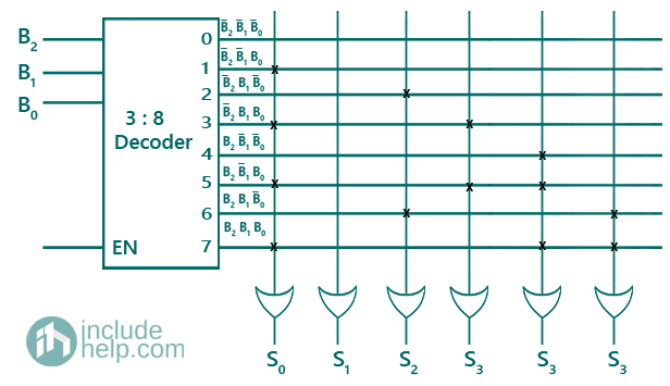
Design a combinational circuit using PROM. The circuit accepts a 3-bit number and generates an output binary number equal to the square of the input number.
Solution
The truth table for displaying squared binary numbers for the corresponding 3-bit binary number is given as:
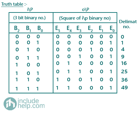
Therefore, S0 (B2, B1, B0) = ∑ m (1,3,5,7)
S1 (B2, B1, B0) has no min-terms.
S2 (B2, B1, B0) = ∑ m (2,6)
S3 (B2, B1, B0) = ∑ m (3,5)
S4 (B2, B1, B0) = ∑ m (4,5,7)
S5 (B2, B1, B0) = ∑ m (6,7)
Logic Diagram: Since, there are three input variables = B2, B1, B0, therefore we will be using a 3:8 decoder.