Home »
Digital Electronics
Realization of Boolean Expressions using only Universal Gates
In this tutorial, we will learn about the Realization of Boolean Expressions using only Universal Gates in Digital Electronics.
By Saurabh Gupta Last updated : May 10, 2023
We already know that NAND and NOR are recognized as the universal gates using which we can perform the functioning of any other logic gate. Thus, any Boolean Expressions can also be realized using NAND/NOR Gate only.
Generally, in Digital Electronics, the minimal Boolean expression are obtained either in SOP (Sum of Products) form or POS (Product of Sums) form. Sometimes, it can also be found in a hybrid of both forms. If the Boolean expression is in SOP form then NAND gates should be used for realization, on the contrary, if POS form is available we use NOR Gate for the realization of the logic circuit.
Realization of Boolean Expressions using only Universal Gates
Once, we perform realization using hybrid AOI logic, then there may arise a case of multilevel logic which results in non-uniform propagation delay between input and output which results in a logic race. However, in case of realization using the universal gates, they give rise to two-level logic. Two-level logic provides a uniform delay between the input and output because each input signal has to pass through two gates to reach the output. So, there are no chances of logic race in realization using universal gates.
Concerting any AOI Logic into NAND/NOR Logic
Any AOI logic can be converted into NAND/NOR logic following some steps which are listed below.
- Step 1: Draw the circuit in AOI logic.
- Step 2: If the circuit is to be drawn only using NOR Gates, we have to add a circle at the output of each OR Gate and the input of each AND Gate.
- Step 3: If the circuit is to be drawn only using NAND Gates, we have to add a circle at the output of each NAND Gate and the input of each OR Gate.
- Step 4: Now, add or subtract an inverter on each line where we have drawn a circle in steps 2 or 3 so that the polarity of signals on those lines remains unchanged from those of the original diagram.
Example 1: Realize the Boolean expression
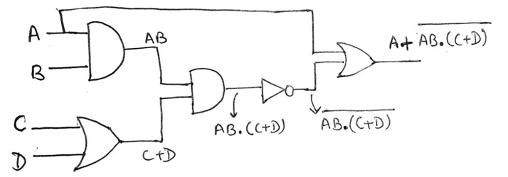
Y = A + AB.(C + D), Using only (a) NAND Gate and (b) NOR Gate
Solution
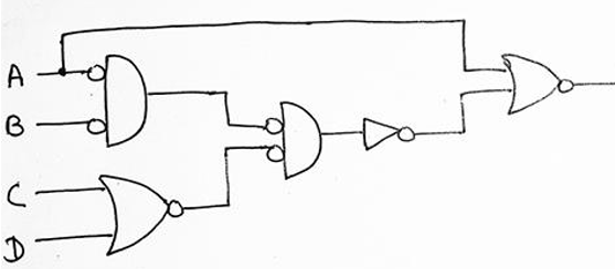
Our first step is to draw the circuit using AOI logic which can be drawn as:
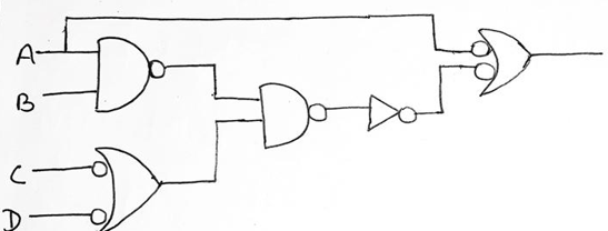
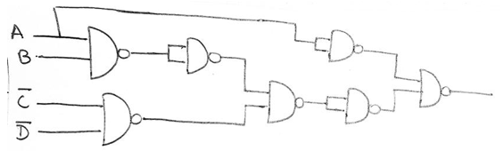
(a) For realization using NAND logic, we will follow step 3, and add a circle to the output of each AND gate and also at the inputs of each OR gate which can be shown as,
Now, moving on to step 4, we have to add or remove an inverter on every line where we have drawn a circle in the previous step which can be shown as
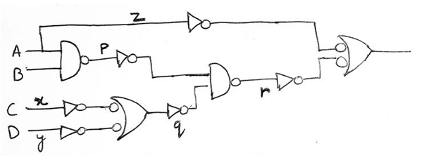
We have added inverters at line x, y, z, p and q as a circle was drawn here, also in the line r addition of an inverter is not required since two circles were drawn and adding two inverters will cancel out each other.
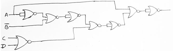
Therefore, the final circuit using only NAND can be represented as,
(b) For realization using NOR logic, we will follow step 2, and add a circle to the output of each OR gate and also at the inputs of each AND gate which can be shown as,
Now, moving on to step 4, we have to add or remove an inverter on every line where we have drawn a circle in the previous step which can be shown as,
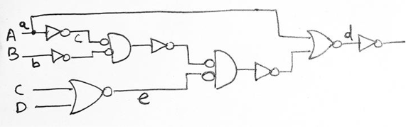
We have added inverters at line a, b, c and d as a circle was drawn here, also in the line e addition of an inverter is not required since two circles were drawn and adding two inverters will cancel out each other. Therefore, final circuit using only NOR can be represented as,