Home »
Digital Electronics
SR Latch in Digital Electronics
Digital Electronics | SR Latch: In this tutorial, we will learn about the SR latches, how they are designed and what are the operations formed by these latches?
By Saurabh Gupta Last updated : May 11, 2023
Latch
The word latch means "to lock". A Latch is an example of a bistable multivibrator (the device which has two stable states). In the first stable state is the high-output and the second one is low-output. A Latch contains a feedback path from which the information can be retained by any device. So, we can conclude that latches are memory devices that are capable to store one bit of data when the power supply is provided. Designing of latches will be similar to flip-flops, but they do not have clocks.
SR Latch Working and Construction
SR latch (Set/Reset) works independently of clock signals and depends only upon S and R inputs, so they are also called as asynchronous devices. SR latch can be created in two ways- by using NAND gates and also can be implemented using NOR gates. SR latch created by NAND gates is sometimes called an inverted SR latch.
1. Working of SR NOR Latch
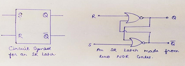
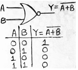
For understanding the working of SR NOR latch, we need to have a look at the truth table of the NOR gate (given below) which shows if any of the input is 'high' output becomes 'low', irrespective of the other input.
Case 1: When R=0 and S=0
Let us suppose, initially the value of Q be 0 then, both the inputs of lower NOR gate becomes zero, and output of that gate becomes 1 i.e., Q'=1, now in the upper gate inputs provided will be 0 and 1, so from truth table of NOR gate we know the output will be low hence Q=0.
From this observation, we can conclude that output in the next state remains the same as the output in the previous state. This condition of the latch is known as Memory condition / Hold state / Latched state.
Case 2: When R=1, S=0
When R=1 and S=0, then at the upper NOR gate, we will receive output as 0 i.e., Q=0, now at the lower NOR gate we have both inputs as 0, so the output Q’=1. Thus, this condition of the latch is known as Reset Condition.
Case 3: When R=0, S=1
In this case, output at the second NOR gate will be 0 i.e., Q’=0, now at first NOR gate inputs provided will be both 0, so the output will be Q=1. Thus, this condition of latch is known as Set Condition.
Case 4: When R=1, S=1
At both gates, we will gate output Q and Q'=0, which is absurd and does not follow the basic working of latch, both Q and Q' must be complementary to each other. So, this condition of latch is known as Invalid state/Race-Around condition/Forbidden state.
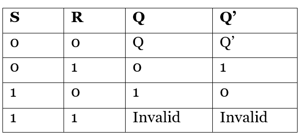
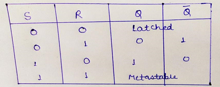
Thus, above all cases of the latch can be summarized in a truth table as:
2. Working of SR NAND Latch
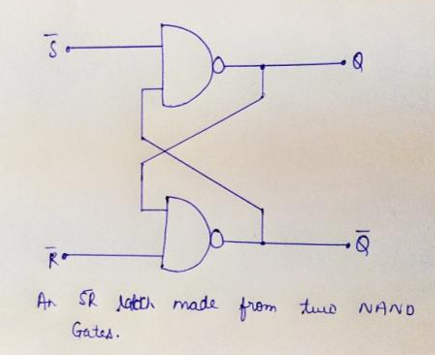
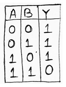
To understand the working of SR NAND latch, we need to have a look at the truth table of NAND gate given below.
Case 1: When S=0, R=0
Let us suppose, the value of Q at the start of the circuit be 1, then inputs at the lower gate will be 1, thus from truth table of NAND gate, we can say that output of the lower gate will be 0 i.e., Q’=0, as a result, input at the upper gate will be 0 & 1. We know, if any of the inputs of the NAND gate is low, the output will always be high, thus Q=1.
Therefore, we can observe the output in the next state to be the same as in the previous state. So, this condition of the latch is known as Memory state/Hold condition.
Case 2: When S=0, R=1
The inputs provided to the lower gate is 0, thus output will be high i.e., Q'=1. Now, at the upper gate inputs provided are 1, thus output Q=0. This condition of latch is known as Reset Condition.
Case 3: When S=1, R=0
In this case, one of the outputs at upper gate will be 0, thus we will get Q=1, similarly inputs at lower gate are 1 and 1, so we get output Q'=0. This condition of latch is known as Set Condition.
Case 4: When S=1, R=1
In this case, one of the inputs of each gate will be low, and we know if any of the inputs of the NAND gate is low its output will be high, so both Q and Q'=1, which is not possible, thus we neglect this condition. This condition of the latch is known as Invalid state / Race-Around condition / Forbidden state.
All the above cases of the latch can be summarized in the table as: