Home »
Embedded Systems
How to Blink an LED Using AVR and Atmel Studio?
In this tutorial, we will learn how to blink an LED (ON and OFF) using an AVR microcontroller and Atmel Studio, and how to write a C program for an AVR microcontroller to blink an LED.
By Suryaveer Singh Last updated : May 12, 2023
Blink an LED Using AVR and Atmel Studio
This is one of the basic programs, or we can say that a type of "HELLO WORLD" program of an Embedded System. The programming in Embedded System quit simple, it is almost similar to the Basic C programming that we use. The programming of Embedded System (AVR) is done using the application ATMEL STUDIO 6.2.
C Program to Blink an LED using AVR
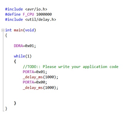
#include <avr/io.h>
#define F_CPU 1000000
#include <util/delay.h>

int main(void)
{
	DDRA = 0x01;

	while(1)
	{
		PORTA = 0x01;
		_delay_ms(1000);
		PORTA = 0x00;
		_delay_ms(1000);
	}

	return 0;
}
Screenshot of the program from editor
Explanation
- Here <avr/io.h> is the header file for the AVR, it includes all the functions, classes that are required for our program.
- F_CPU indicates the CPU speed of our ATMEGA16(AVR).
- The header file #include <util/delay.h> provides the delay that is required in the program. It is basically used to delay the operation performed.
- Below the int main(void) we write the pins that are given to our ATMEGA16 board by the LED and is denoted by DDRA = 0x01, where 0x represents the hexadecimal and 01 is the is the position of the LED attached to it.
- Inside the while(1) we write the coding which we want to repeat continuously.
- Inside the while loop PORTA = 0x01 represents the condition when our LED blinks i.e. the LED will be on when we will receive 1 in our PA0 port and will be OFF if we receive 0.
- _delay_ms(1000) shows the delay is micro seconds which we have used 1000.
Simulation
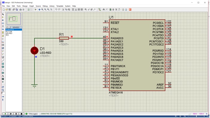
Simulation Explanation
- Open the PROTEUS Professional and from the file Menu open a NEW design
-
Then go to the left side in the selection Mode, click on P and select the following devices:
- ATMEGA16
- RESISTANCE
- LED of any colour
- From the terminal mode on the left side, select the Ground terminal and place it as shown in the figure.
- Arrange all the components as shown in the aboveimage.
- Here we have not connected any power terminal, because during the simulation it is not required.
- Now double click the resistance and change its value from 10k to 330 also double click the ATMEGA16 and a popup will appear there select the file of the that has been created in your respective directory through ATMEGA STUDIO 6.2.
- Open the debug file and select the HEX File and open it.
- Now go to the left bottom corner and click on play.
- Through these Steps the program and Stimulation will be executed and your LED will burn with the respective delay.