Home »
Embedded Systems
Categories of Addressing Modes of 8086 Microprocessor
In this tutorial, we will learn about the various addressing modes of the 8086 Microprocessor. We will first discuss what does addressing mode mean? After that, we will study their different categories in brief.
By Monika Sharma Last updated : May 15, 2023
Addressing Modes
Addressing modes are the one which the where the operand (source or destination) are stored, i.e. any memory location or any internal register.
Categories of Addressing Modes
There are a few categories of addressing modes which are as follows:
- Immediate Addressing Mode
- Absolute/ Direct Addressing Mode
- Register Addressing Mode
- Register Indirect Addressing Mode
- Indexed Addressing Mode
- Register Relative Addressing Mode
- Based Indexed Addressing Mode
- Relative Based Indexed Addressing Mode
- Data Memory Addressing Modes
- Program Memory Addressing Mode
- Stack Memory Addressing Mode
1. Immediate Addressing Mode
In this addressing mode, the operands are specified within the instructions. What this means is that the instruction will either contain the values itself or will contain the operands whose values are required.
Example:
MOV AL, 28H
ADD AX, 2314H
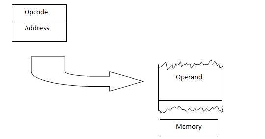
2. Absolute/ Direct Addressing Mode
In it, a 16-bit memory address (offset) or an input/ output address is directly specified in the instruction as a part of it.
3. Register Addressing Mode
In this type of addressing mode, the operands (or the values) are stored within any of the internal registers itself. So, the processing on these operands is done either in those registers itself or by shifting their values to some other registers.
Some examples of Register Addressing mode are:
ADD AX, BX
MOV AL, BL
SUB BL, AL
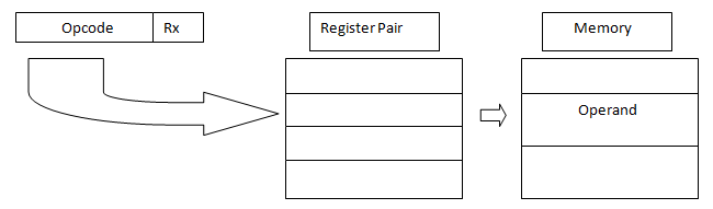
4. Register Indirect Addressing Mode
In this offset address of data is in either Bx, SI, DI, (Base register, source index or Destination index) default segment is either DS or ES.
Data is supposed to be available at the address pointed to by the content of any of the above registers in the default data segment.
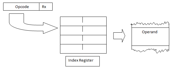
5. Indexed Addressing Mode
Here, offset of the operand is stored in one of the index registers. DS is the default segment for SI and DI in string instruction DS and ES default segment for register SI and DI.
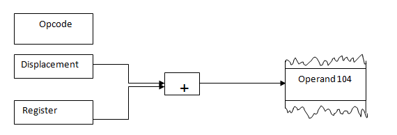
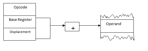
6. Register Relative Addressing Mode
In it, data is available at an effective address formed by adding an 8 bit or 16-bit displacement with content, any one of the registers Bx, Bp, SI, DI in the default (DS or ES) segment.
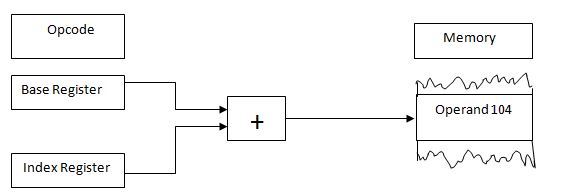
7. Based Indexed Addressing Mode
The effective address of data is formed by adding content of base register Bx or Bp to the content of index register.
8. Relative Based Indexed Addressing Mode
Here the effective address is formed by adding an 8 bit or 16-bit displacement with the sum of the content of any one of the index registers in the default segment.
9. Data Memory Addressing modes
In these types of addressing modes, the offset address of the operands is mentioned in the instructions. So, in the Data Memory Addressing mode, first the offset address is calculated after that memory location is calculated, and then the data stored at that location is fetched.
Some examples of the Data memory Addressing modes are:
MOV AL, [2000H]
MOV AL, [BX]
The Data memory addressing mode is further categorized into various types about which we will discuss in the upcoming articles.
10. Program Memory Addressing Mode
These types of addressing modes are used in branch instructions like JMP or CALL instruction.
Example:
JMP 0006H
Note: The Data memory addressing mode and the Program Memory Addressing mode are further categorized into various types about which we will discuss in the upcoming articles.
11. Stack Memory Addressing Mode
The stack memory addressing mode is used whenever you perform a push or pop operation. Always a word will be entered or popped from the stack in this addressing mode, and the value of the Stack Pointer (SP) will be incremented or decremented accordingly. The higher byte of data will be stored at SP-1 location and the lower byte of data will be stored at the SP-2 memory location.
Example:
PUSH BX
Here, suppose BX=1234H and SP=2000H
So, the byte 34H will be stored at 1999H and byte 12H will be stored at 1998H location.