Home »
Embedded Systems
PIN Diagram and Registers of 16x2 LCD
In this tutorial, we will learn about the PIN diagram and registers of 16x2 LCD Display.
By Suryaveer Singh Last updated : May 12, 2023
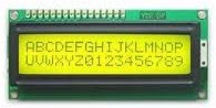
16x2 LCD Display
In these years the LCD is finding widespread use. It has replaced the LEDs or other multi-segment LEDs.This is due to the following reasons:
- The declining price of LCDs.
- The ability to display numbers, characters and graphics. This is in contrast to LEDs which are limited to numbers and a few characters.
- Ease of programming of character and graphics.
16x2 LCD PINs and PIN Diagram
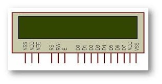
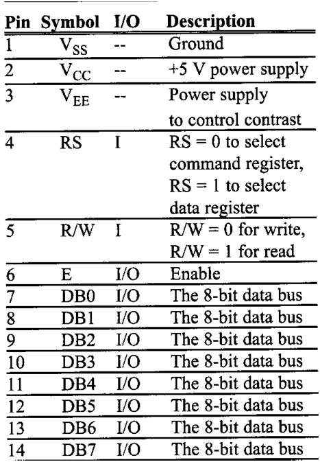
The LCD that we are discussing here in this section has 14 pins. The function of each Pin is given below:
16x2 LCD Display PIN Diagram: PINs Registers
1. Vcc, Vss and VEE
Vcc and Vss provide +5V and ground to our LCD, respectively, VEE is used for controlling LCD contrast i.e. dimming the brightness or increasing the brightness of LCD.
2. RS (Register Select)
There are two very important registers inside the LCD. The RS pin is used for the selection of these registers. If RS=0, the instruction command code register is selected, which allows the user to send commands for the LCD such as clear display, cursor at home, and so on. If RS=1, the data register is selected. It allows the user to send data that is to be displayed on the LCD.
3. R/W (Read/Write)
R/W inputs allows the user to write information to the LCD or read information from it. R/W is set 0 while reading and R/W is set 1 when writing.
4. E (Enable)
The enable pin is used by the LCD to latch information presented to its data pins.
When data is supplied to the data pins, a high-to-low pulse must be applied to this pin in order for the LCD to latch in the data present at the data pins. This pulse must be a minimum of 450ns wide.
5. D0-D7
The 8-bit datapins, D0-D7 are used to send information to the LCD or read the contents of the LCD’s internal Registers. We send the ASCII codes is sent to the LCD to display numbers and letters for the letter A-Z, a-z, and numbers 0-9 to these pins while masking RS=1.
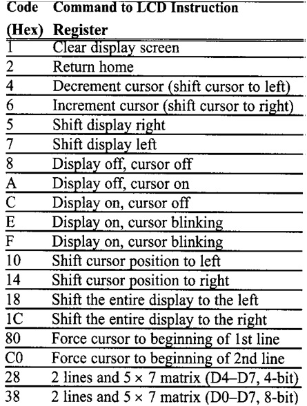
There are also instruction command codes that can be sent to the LCD to clear the display or force the cursor to the home position or blink the cursor.
The next table here incudes all the instruction command codes. To interface LCD to the AVR we can use 4-bit mode and 8-bit mode. The 8-bit data interfacing is easier to program but uses 4 more pins.