Home »
Embedded Systems
Pin Diagram and Description in 8086 Microprocessor
Pin Diagram of 8086 Microprocessor: In this tutorial, we will learn about the Pin diagram and description of the 8086 Microprocessor with their meaning and purpose.
By Monika Sharma Last updated : May 15, 2023
Pin Diagram of 8086 Microprocessor
The 8086 microprocessor is a 40 pin IC in which there are 20 pins on each side of the IC. The diagram of the same is as follows:
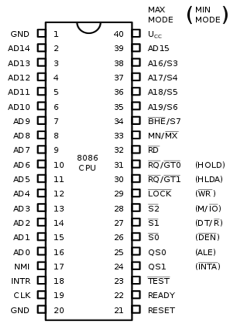
Image source: https://images.app.goo.gl/JQw5Fqvjv7mfxSP97
Pin Description of 8086 Microprocessor
The PIN description, meaning, and purpose of each PIN are given as follows -
AD0 to AD15
These lines are multiplexed unidirectional address and status bus. What this means is that at time T1, they carry status signals and in remaining cycles, they carry status signals.
- S6 is used as bus master, which handles the internal bus control.
- S5 is used as interrupt flag.
- S4 and S3 are used to select the segment out of the four segments.
| S4 | S3 | Segment selected |
| 0 | 0 | ES |
| 0 | 1 | SS |
| 1 | 0 | CS |
| 1 | 1 | DS |
BHE' / S7
BHE stands for Bus High Enable. It is an active low signal, i.e. it is active when it is low. It is used to indicate the transfer of data over the higher order data bus (D8 to D15).
BHE' decides whether the data bus will carry 16-bit data or 8-bit data. When BHE’ is enabled (i.e. 0), then the bus will carry 16-bit data, else only 8-bit data through the lower order data bus lines. It is multiplexed with status pin S7.
RD'
It is a read signal used for read operation. It is also an active low signal.
READY
This is an acknowledgment signal from the slower I/O devices or memory. When high, it indicates that the device is ready to transfer data, else the microprocessor is in the wait state.
RESET
By using this pin, the program control returns to FFFF0H.
INTR
This pin is used to receive an interrupt request signal. It is a type of maskable interrupt.
NMI
This is used for Non-Maskable Interrupt Request.
GND
There are two ground pins in the 8086, pin 1 and pin 20.
VCC
The pin 40 is for voltage input.
MN / MX'
This pin is used for minimum or maximum mode of the microprocessor. When this pin is 1, the microprocessor works in minimum mode, and when the pin is at 0, the maximum mode is followed.
Minimum and maximum Mode Pins
Total 8 pins, from Pin 24 to pin 31 work differently for different modes (maximum or minimum).
TEST'
This is also an active low signal. This pin is used for wait instruction when the 8086 is connected with the 8087 microprocessor.
CLK
This pin tells about the clock pulse.