Home »
CATIA Tutorial
CATIA – Construction of Cuboid
Learn how to create/ construct a cuboid in CATIA V5?
Submitted by Benisha Lama, on February 22, 2022
Assuming that you already have the software, we'll head right away into this tutorial by opening the CATIA software.
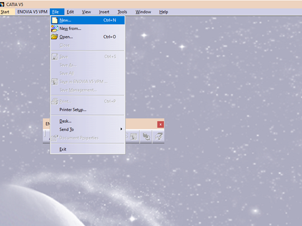
Step 1: Open the software from your desktop. After it gets open, a window same as below will be displayed. Proceed further by clicking on FILE from the Title Bar. From the drop-down, click on the New option.
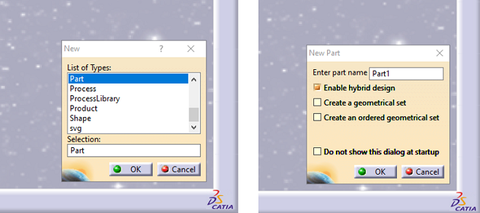
Step 2: A dialog box will appear; different types of options will appear and from that select PART. Another dialog box will appear according to one's choice, the default name will be shown as "Part 1" but it can be changed.
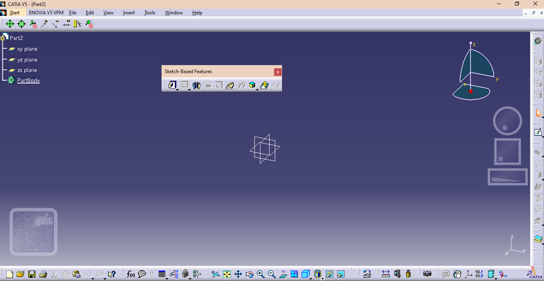
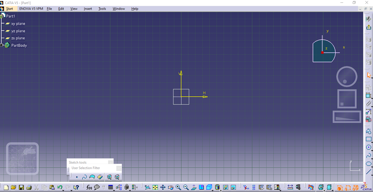
Step 3: Clicking OK on the dialog box, the Part will be created and your window will look like this.
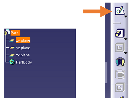
Step 4: From the part chain tree on the left side, select the plane. XY plane has been chosen for this tutorial. After selecting the plane, click on the sketch icon to sketch the required rectangle.
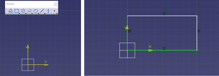
A window like below will appear.
Step 5: From the profile dialog box, select the rectangle option as in order to create a cuboid you need to sketch the rectangle first.
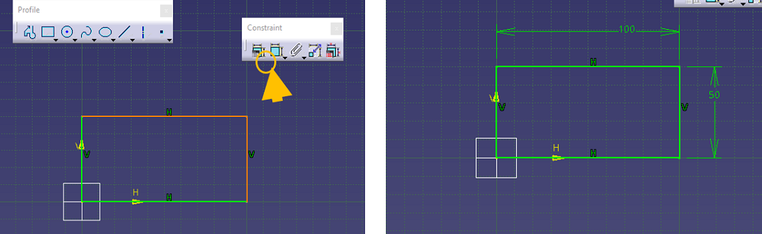
Step 6: Rectangle is created but all sides of the rectangle are not yet constrained. By constraining, degree of freedom of sketch is restricted so this step should never be left out. Selecting the sides which have not been constrained, moving to the constraint dialog box and licking on the constrain option, constrain the sketch.
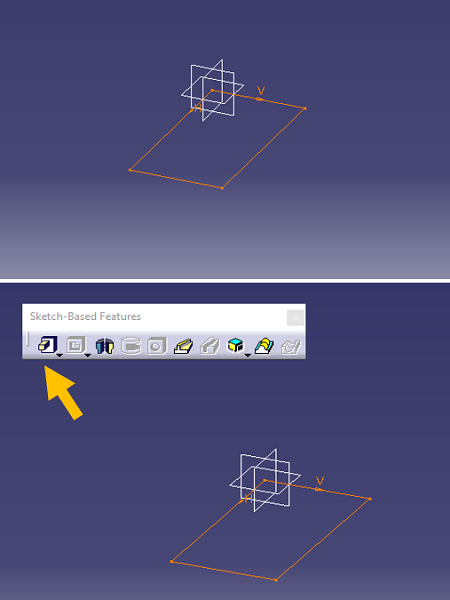
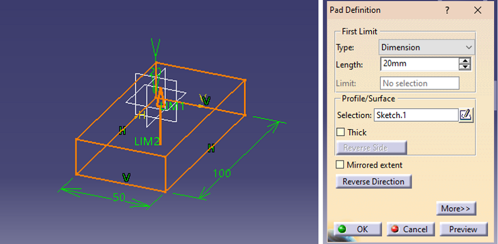
Step 7: Exit the sketch mode. The rectangle will look like this. Then go to the sketch feature and choose the pad option to create the cuboid.
Step 8: The rectangle will develop the cuboid shape. From the pad definition dialog box, set the required dimensions and click on OK.
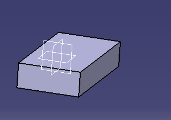
Result:
Advertisement
Advertisement