Home »
CATIA Tutorial
CATIA – Utilizing Translation Feature
Learn how to utilize translation feature in CATIA?
Submitted by Benisha Lama, on March 05, 2022
Translation:
The translation feature is used to moves an object a certain distance. The object is not altered in any other way. It is not rotated, reflected, or re-sized. The object is just moved from one place to another in an efficient manner.
Step 1: Start by opening the software, then proceed to open a new file then select a Part design.
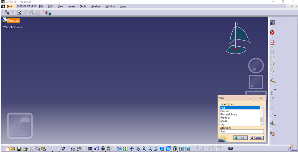
This screen will be displayed.
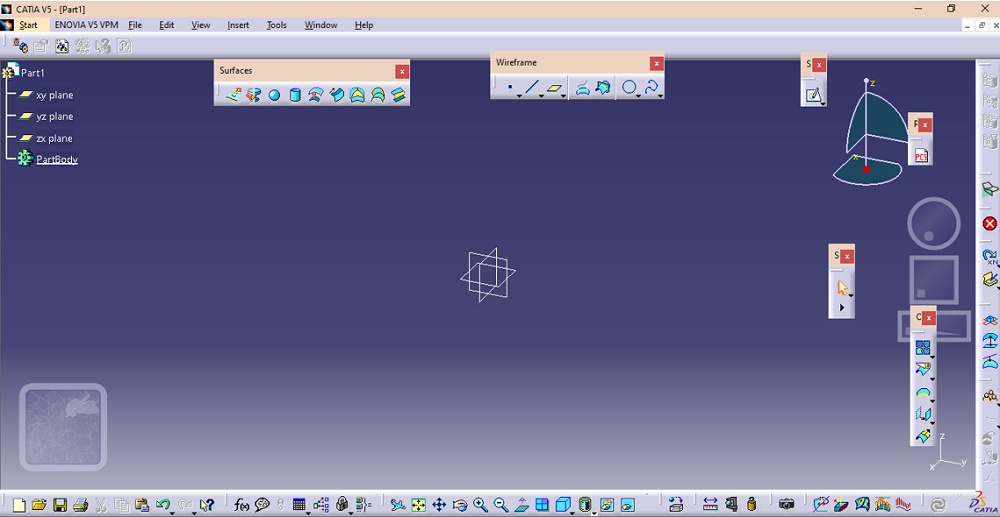
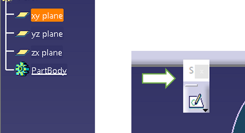
From there click on the sketch option after selecting the plane on which the design has to be created.
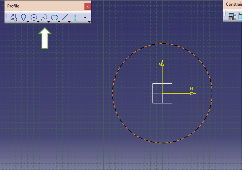
Step 2: In the sketch workbench, choose the circle option from the profile dialog box. Drag your cursor and draw the circle keeping the origin as the center.
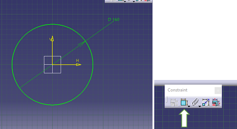
Step 3: Constraint the circle using the constraint option and set the radius of the circle.
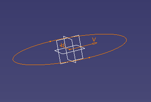
Step 4: Exit the sketch workbench. The circle will look this way.
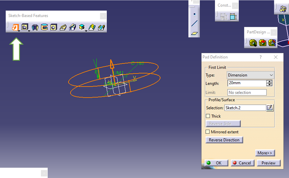
Step 5: Give definition to the sketch by clicking on the Pad option from the sketch-based feature. Set the required dimension and click OK.
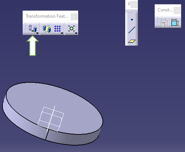
Step 6: To translate the object to a different place for the transformation feature dialog box, choose the translation feature.
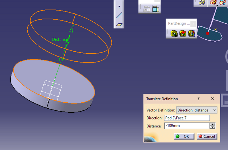
Step 7: Set the distance to which you want the object to be moved. It can be moved to the reversed direction as per requires. Click Ok when all the parameters have been set.
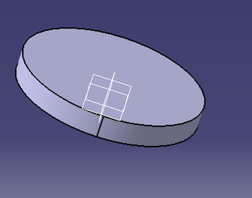
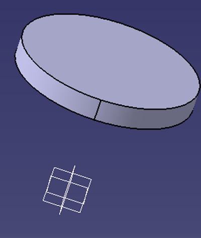
Result:
Advertisement
Advertisement