Home »
Embedded Systems
Architecture of 8086 Microprocessor
In this tutorial, we will learn about the architecture of the 8086 microprocessor. We will first see a block diagram explaining the layout of the components of the microprocessor and will then explain the diagram briefly describing each of its components.
By Monika Sharma Last updated : May 15, 2023
As discussed earlier, the 8086 microprocessor consists of two main blocks: the Bus Interface Unit (BIU) and the Execution Unit (EU). All the components of the 8086 microprocessor are present within these two blocks. Let us study the layout of the 8086 with the help of the following block diagram:
Architecture of 8086 Microprocessor Diagram
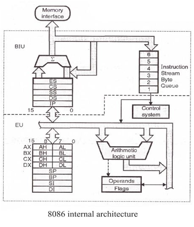
Image source: https://images.app.goo.gl/Yuunw7aMkezbqpzcA
It is clear from the diagram that only the BIU has a direct link with the memory. This memory can be directly accessed either by the segment registers, the Instruction Pointer (IP) or the Instruction Queue for fetching up the instructions.
These instructions are sent in the Control Unit for execution. The control unit takes the help of General Purpose registers, Index registers and Pointers, operands, flags and the most important, the Arithmetic Logic Unit (ALU). All these are part of the Execution Unit.
1. Bus Interface Unit (BIU)
1.1. Bus Interface Unit (BIU)
The Instruction Queue contains the set of instruction which is to be executed. To make the processing faster, the 8086 pre-fetches up to 6 instructions in advance and stores them in the Instruction queue. So, whenever one instruction completes its execution, the control unit need not wait for the next instruction to be fetched and then brought for execution because this job is already done and the next instruction that is to be executed is ready in the Instruction queue.
1.2. Segment Registers
Each Segment register can work with 16 bits of binary data. There are 4 types of segment registers:
- CS: Code Segment Register
- DS: Data Segment Register
- SS: Stack Segment Register
- ES: Extra Segment Register
1.3. Instruction Pointer
The Instruction pointer contains the address of the next instruction that is to be executed.
2. Execution Unit (EU)
2.1. Control Unit (CU)
All the Instructions are executed inside the Control Unit. It is the main component which is responsible for the processing of any processor.
2.2. Arithmetic Logic Unit (ALU)
All the Mathematical and Logical Operations are performed inside the ALU. So, if any instruction needs to perform such operation, the Control Unit handovers it to the ALU.
2.3. Flag Register
The flag Register is of 16-bit length which consists of 9 flags, and the rest 7 bits are of don't care cases.
2.4. General Purpose Registers
The General Purpose Registers are used as containers for storing the values which may be required for executing the instructions. Each General Purpose Register consists of 16 bits. There are 4 types of General Purpose Registers:
- AX = [AH:AL]
- BX = [BH:BL]
- CX = [CH:CL]
- DX = [DH:DL]
2.5. Pointers and Index Registers
The 8086 contains following Pointers and Index Registers. (Here, IP is not mentioned because it is a part of the BIU)
- BP: Base Pointer
- SP: Stack Pointer
- SI: Source Index
- DI: Destination Index
2.6. Operands
These may be used within the instructions.
Conclusion
In this tutorial, we explained everything about the Architecture of 8086 Microprocessor, including its internal architecture, i.e., the diagram of 8086 Microprocessor, parts of the execution units. If you have any questions, you can leave a comment below.