Home »
Embedded Systems
Data Flow Diagram of 8255 PPI (Programmable peripheral interface)
In this tutorial, we will learn about the data flow diagram of the 8255 PPI, in which we will learn how the data flows within the 8255 IC and how all the functionalities are performed?
By Monika Sharma Last updated : May 22, 2023
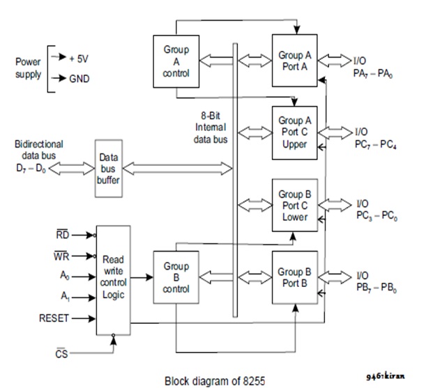
The data flow diagram of the 8255 PPI given above shows the internal working of the IC hoe data is transferred within it and what pins perform these functions. It is further explained as follows:
Internal Bus
Here, you can see that we have 8 bit of internal bus for the 8255 PPI. Therefore, only 8 bits of data can be transferred between the 8255 IC and the interfaced device at a time.
Data Bus Buffer
The data bus buffer performs the transfer of 8 bits of data from the 8255 PPI to the microprocessor or other devices it is interfaced with.
Power Supply
Here, we have 1 pin for +5V of power supply and 1 pin for ground voltage.
Read- Write Control Logic
As the name suggests, the Read Write control logic is responsible for all the read-write operations happening in any of the ports. It is controlled by the following pins:
- RD': For reading data, it should be reset.
- WR': For writing data, it should be reset.
- A0 and A1: These two pins together decide which port or control word will be selected for data transferring purpose.
- RESET: It sets all the pin to their default values.
- CS': For chip selection.
Group A control
This unit controls the ports that fall under group A, i.e. Port A and Port C- upper.
Group B control
This unit controls the ports that fall under group B, i.e. Port B and Port C- lower.
Group A- Port A
It is the port A which contains its 8-bit data lines for I/O purpose, and it is controlled by the Group A control.
Group A- Port C upper
It contains the higher 4-bit data lines of port C. It is also controlled by the Group A control since it falls in group A category.
Group B- Port B
It is the port B which contains its 8-bit data lines for I/O purpose, and it is controlled by the Group B control.
Group A- Port C upper
It is the lower half of the Port C, i.e. it contains the lower 4-bit data lines of port C. It is also controlled by the Group B control.
Advertisement
Advertisement