Home »
Embedded Systems
AVR | Using a Motor Driver to Run Motors
In this tutorial, we will learn the use of a Motor Driver (L293D), which we will use to increase the revolution of Motors to a faster state.
By Suryaveer Singh Last updated : May 12, 2023
Run Motors Using a Motor Drive
The coding used here will be similar to the last coding in which we used to run two motors along with their individual switch.
The concept used here will be also similar to the last program that we created.
I'll try to again explain you all the things shortly.
C Program to Run Motors Using a Motor Drive
#include<avr/io.h>

int main(void)
{
	DDRA=0x00;
	DDRD=0x33;
	while(1)
	{
		if((PINA & 0x03) == 0x03)
		{
			PORTD=0x11;
		}
		else if((PINA & 0x03) == 0x02)
		{
			PORTD=0x01;
		}
		else if((PINA & 0x03) == 0x01)
		{
			PORTD=0x10;
		}
		else if((PINA & 0x03) == 0x00)
		{
			PORTD=0x00;
		}
	}
	return 0;
}
Explanation
- Here, DDRA=0x00 represents the inputs that are to be given by both the buttons which are connected in the PORT A.
- DDRD=0x03 represents the terminals in which our Motors are connected. Motor 1 is connected in terminal PD0 and PD1 while our motor 2 is connected in PD4 and PD5.
PD7		PD6	PD5	PD4	PD3	PD2	PD1	PD1
0		0	1	1	0	0	1	1
In the bottom line 0011 means 3 in hexadecimal so it is written as DDRD=0x33.
The first if statement states our condition 11, this is the condition when our both the buttons will be pressed and our both the motor will rotate here.
Inside the, if statement PINA & 0x03 is basically a statement which tells us the condition of number of button Pressed.
If both the buttons are pressed (0x03) then PORTD==0x11 i.e. both the motors will run simultaneously.
If only second button is pressed (0x02) then PORTD==0x01 i.e. only first motor will start to rotate.
If only first button is pressed (0x01) then PORTD=0x10 i.e. only second motor will start to run.
That last condition states that if no button is pressed (0x00) i.e. PORTD==0x00, here no motor will run.
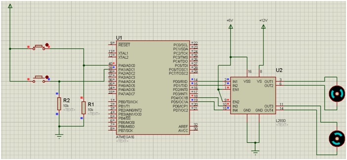
Simulation
Simulation Explanation
-
Device Required:
- Two Resistors of 10k ohm
- Ground Terminals
- Power Terminals
- Two push buttons
- Atmega16
- Two simple Active DC motors (double click on them and change the value from 12v to 3v)
- L293D motor Driver
- Arrange the components as shown in the figure above.
- This time connect the output pins of ATmega16 to the input pins of the Motor Driver as shown.
- Then connect the output pins of the motor driver to Both the Motors as shown in figure.
- Connect both the GND pins of the motor driver to the ground terminal.
- Connect VSS, EN1, EN2 pins to the Power terminal as shown.
- Double click on this power terminal and assign it a value of +5v.
- The VS terminal of motor driver always remains on high potential more than normal. Therefore we have assigned it a value of +12v.(Double click on it and assign the value of +12v).
- Change the motor voltage value as mentioned above.
- Debug the HEX file in the ATmega16.
- Click on the play button and your simulation will start.
Here, you will notice that your motors will be revolving faster than the last program you created. This is all due to the motor Driver (L293D) that we have created here and this explains the Basic principal/use of the Motor Driver.
Advertisement
Advertisement