Home »
Embedded Systems
AVR | Masking
In this tutorial, we will learn about the masking is with the help of example/ C program.
By Suryaveer Singh Last updated : May 12, 2023
What is Masking?
In simple words, Masking is a process in which we hide the information that is not required.
For example, we have eight switches connected to the PORTD of our ATmeg16, one Switch to each pin of PORTD, and just for instance we want to read only PD3 and PD4, in this case we would use The Masking process to hide our remaining information.
The simple way to achieve this can be done by AND mask:
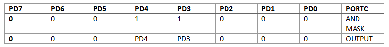
Here, we have performed Bitwise AND operation on the output that we received initially through PINX command.
The simple thing that we are doing here is that the information that we need to hide is AND operated with 0, and the information that we need is AND operated is 1.
In the above Example, we only needed information of PD3 and PD4 so we masked with 1 and other pins we masked with 0.
In order to keep the information we also do OR masking in which we do bitwise OR operation with 1.
The process of masking can be used at both times i.e. while providing information about Pins or reading information from the Pins.
So this was all that you need to know about masking, now we would learn through a simple example about the Process Masking.
Masking Example in AVR Microcontroller
Below is an example, in which we will use masking. The things that we are required to do in this code is that we have to blink two LED such that one of the LED is always on and the other LED will be on only if we press the button otherwise it would be off.
#include <avr/io.h>

int main(void)
{
	DDRA = 0x00;
	DDRD = 0x03;
	PORTD = 0x01;


	while(1)
	{

		if(PINA & 0x01)
			PORTD |= 0x02;
		else
			PORTD &= (0xFD);
	}
}
Explanation
- The line int main(void) indicates that the LED is off by default.
- DDRA=0x00 is for the button attached.
- DDRD=0x03 is for Led that is connected to PIN0 and PIN1.
- Inside the while loop if (PINA & 0x01) represents the condition in which the button is pressed.
- Here, we have used OR operator because we don’t want to stop our first LED to stop glowing. This OR operator will provide us with information for both the LED together.
- The else condition is written in such a manner that we have masked the information that our first LED is glowing and we have stopped the second LED from glowing because in the else condition our switch is OFF.

Hence, when button is not pressed only our first LED will glow (explained in above table).
Simulation
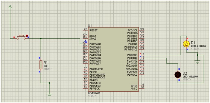
Simulation Explanation
-
Components required:
- 2 ground terminals
- 1 resistor
- 1 power terminal
- ATmega16
- 2 LEDs
- 1 button
- Connect the components as shown in figure.
- Upload the hex file in the ATmega16.
- Start the simulation, you will notice that the LED1 will glow continuously while the second LED will only glow if the Button is pressed.
Advertisement
Advertisement