Home »
Embedded Systems
The 8255 programmable IC
Here, we are going to learn about the 8255 programmable IC: its introduction, ports of 8255, architecture of 8255, pin diagram, modes etc.
Submitted by Ayush Sharma, on November 02, 2018
Introduction
An 8255 programmable integrated circuit (IC) is an IC used for interfacing the microprocessor with the peripheral devices. It is a 40 pin IC which was introduced by INTEL to use with its 8085 and 8086 microprocessors.
Ports of 8255
There are three input/output 8-bit ports in this IC namely port A, port B, port C. The port C can be divided into two each of 4 bits(C upper and C lower) according to requirement.
Architecture of 8255
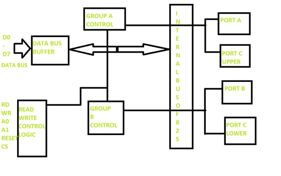
Pin diagram of 8255
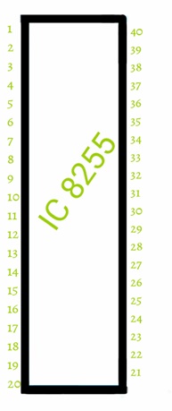
- The pins 1-4 and 37-40 are for Port A(PA0-PA7).
- The pins 18-25 are for port B(PB0-PB7).
- The pins 10-17 are for port C(PC0-PC7).
- The pins 27-34 are for data bus(D0-D7) linked to the microprocessor.
- The RD(5) and WR(36) are two low active pins for reading and write operations respectively. When a low signal is sent to the pin no 5 it means a read operation is performing. Similarly, when a low signal is sent to pin no 36 this means the write operation is being performed.
- The CS(chip select) is another low active pin that works as an enable to the IC.
- The A0 and A1 are the control logic at 8 and 9.
- A0 A1
- 0 0 port A
- 0 1 port B
- 1 0 port C
- 1 1 Control Word logic(CWR)
- These select the ports.
- The RESET pin at 35 used to reset the IC.
- The ground(7) and Vcc(26) are also present to establish the potential difference.
Modes of 8255
This IC works in 3 modes
- Mode 0 in which all the three ports act as input-output ports.
- Mode 1 in which only port A and port B act as input-output port while port C is used for handshaking.
- Mode 2 in which only port A is used as a bidirectional port for both input-output.
Control word logic (CWL)
Everything in the 8255 IC is dependent on the CWL. There are 8 bits in the CWL:
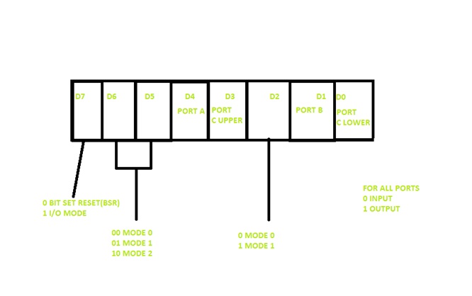
- D0 port Clower
- D1 port B
- D2 Mode
- D3 port Cupper
- D4 port A
- D5 Mode
- D6 Mode
- D7 BSR(Bit Set Reset)/I/O mode
We can set the CWL by using the IN and OUT command of the respective microprocessor.
Advertisement
Advertisement