Home »
Embedded Systems
The BSR Mode of 8255 PPI (Programmable peripheral interface)
8255 BSR Mode: In this tutorial, we will learn about the working of 8255 PPI in the BSR mode. We will first learn how the pins of the 8255 IC are set or reset while it is in the BSR mode and what functionalities can be performed by it in this mode?
By Monika Sharma Last updated : May 22, 2023
The BSR mode stands for "Bit Set Reset Mode". The first bit, i.e. the Most Significant Bit (MSB) of the Control word decides the mode in which the 8255 IC will be. For the IC to be in the BSR mode, the MSB must be reset, i.e. it must be 0. The BSR mode works only for port C. In this mode, we can select any bit of the port C and then assign it any value: either 0 or 1. The following diagram illustrates the control word layout for the BSR mode:
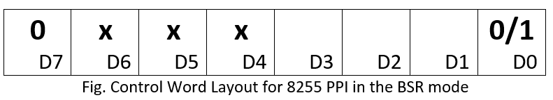
The control word in the BSR mode is as follows,
- Here, you can see that the D7 bit is reset which indicates the BSR mode.
- The next three bits, i.e. D6, D5, and D4 are the don’t care cases which means that no matter what value they contain, either 0 or 1, the processor does not consider them for any kind of operations.
-
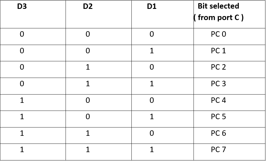
The Next three bits: D3, D2, and D1 decide which bit of the port C must be selected. This is done in the following manner:
- The last bit of the control word, bit D0 is responsible for the selected bit to be set or reset. The processor sets the selected bit of the port C to either 0 or 1 according to the value of D0.
Advertisement
Advertisement