Home »
Embedded Systems
L293D Motor Driver IC
In this article, we would learn about a motor driving IC named as L293D. It is one of the important components in Embedded Systems and also in robotics.
Submitted by Suryaveer Singh, on June 23, 2018
So, an L293D is an integrated chip which is used to control motors in autonomous Robots and also in Embedded Circuits. L293D and L29NE are the most commonly used motor driver IC, these are designed to control two motors simultaneously. L293D has a dual H-Bridge motor Driver integrated circuit. This motor driver acts as a current amplifier. The motor takes a low-signal current and provides a high-output signal at Output. This high signal current is then transferred to the attached Motor.
We can also build H-Bridge in these motor, which can be built from scratch with the help of a Bi-polar junction Transistor (BJT) or with a Field Effect Transistor (FET). For the low current profile, L293 is simple and inexpensive for low current motors and it becomes Expensive. The L293 is limited to s but in reality, it is limited to much smaller current than this. Exceeding temperature in L293 would increase its temperature so, we should have to do some serious heat sinking in it to make it usable.
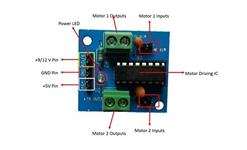
Image source: L293D
Image source: L293D
PINs Diagram of an L293D Chip
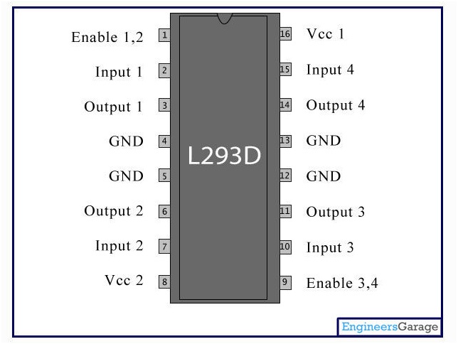
Image source: L293D pins
- 1- Enable 1-2, when this is HIGH the left part of the IC will work and when it is low the left part of the motor will not work.
- 2 - INPUT 1, when this pin is HIGH the current will flow through output 1.
- 3 - OUTPUT 1, this pin should be connected to one of the terminals of a motor.
- 4,5 - GND, ground pins.
- 6 - OUTPUT 2, connect this to one of the terminals of the motor.
- 7- INPUT 2, when this pin is HIGH the current will flow through output 2.
- 8 - VCC2, this voltage will be supplied to the motor.
- 9 - Enable 3-4, when this is HIGH the right part of the IC will work and when it is low the left part of the motor will work.
- 10 - INPUT 3, when this pin is HIGH the current will flow through output 3.
- 11 - OUTPUT 3, connect this pin to one of the terminals of a motor.
- 13,12 - GND,ground pins.
- 14 - OUTPUT 4, connect this pin to one of the terminals of the motor.
- 15 - INPUT 4, when this pin is HIGH the current will flow through output 4.
- 16 - VCC1, this is the power source to the IC. So, this pin should be supplied with 5 V.
After reviewing the L293D you may have come up with the question about why there are 4 grounds in the IC.
The answer is quite simple, as our motor Driver deals with so much current flow; a large amount of heat is generated. So we need a heat sink in Motor Driver to reduce the heat developed in it. While soldering the pins we get so much of metallic area between the grounds where the heat developed is dissipated.
References:
Advertisement
Advertisement