Home »
Embedded Systems
8051 Microcontroller: PIN Diagram and PIN Descriptions
In this tutorial, we will learn about the structure of 8051 family microcontrollers i.e., the 8051 microcontroller PIN diagram and PIN descriptions, and the various ports & functions performed by specific pins in a microcontroller.
By Sudarshan Paul Last updated : May 12, 2023
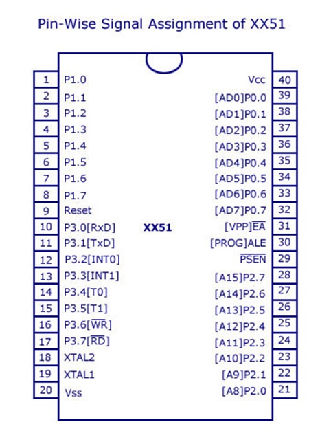
8051 Microcontroller PIN Diagram
8051 Microcontroller PIN Descriptions
1. Pins from 1-8
Port 1: The pins in this port are bi-directional and can be used for input and output. The pins are individually controlled; some are used for input while others are used for output purposes.
2. Pin 9
This pin is also called ‘Reset Pin’. This is used for resetting the microcontroller to its initial values. If the pin is set at logic 0, the chip runs normally. When the oscillator is running, setting the pin at logic 1 for more than two machine cycles will reset the microcontroller.
3. Pins from 10-17
PORT 3: These pins are same as pins in port 1 because of their bidirectional input port.
- Pin 10 and Pin 11 perform receiving and transmitting operation of serial data using ‘RS-232’ protocol.
- Pin 12 and Pin 13 are used to interrupt inputs.
- Pin 14 and Pin 15 perform alternative functions linked with Timer 0 and Timer 1.
- Pin 16 and Pin 17 are used when working with external memory.
4. Pins from 18-19
The pins are used for connecting an external crystal oscillator module with the microcontroller.
5. Pin 20
Also called Vss. This is the ground pin that represents 0V.
6. Pins from 21-28
PORT 2: These are another set of bidirectional input port, they are used when processing external memory. Higher order address bus signals are multiplexed with this quasi-bidirectional port.
7. Pin 29
Also called PSEN (Program Store Enable) it controls and manages the access to external CODE memory.
8. Pin 30
Named as Address Latch Enable (ALE). It is used when working with external memory. ALE activity is disabled in some devices where external memory is not used. Thus helping in reducing the electromagnetic interference generated by the product.
9. Pin 31
Named as External Access (EA). In order to execute code from internal memory this pin is connected to Vcc. To execute code from external memory the pin must be grounded.
10. Pins from 32-39
Port 0: These are set of another bidirectional input port. Unlike Port 1, Port2 and Port 3 this port lacks pull-up resistors.
11. Pin 40
Named as Vcc. This is usually a 5V pin on 5V devices and 3V pin on 3V devices.
12. I/O Pins
The 8051 microcontrollers are mostly 8-bit ports, thus giving a total of 32 pins which you can use to read input and control output. All of them are bidirectional in nature so they can perform as both input and output. Some of the ports perform alternate functions as discussed above such as to support access to external memory. This is done to reduce the size of the microcontroller device. When these ports are busy in performing their alternate functions, they can not be made to act as input-output ports.
Advertisement
Advertisement