Home »
AutoCAD
Drawing Units in AutoCAD 2022
Learn about the procedure to specify the drawing units in a new or existing drawing in AutoCAD 2022.
By Akash Periyasamy Last updated : March 28, 2023
In AutoCAD 2022, units play an important role in determining the way in which a part is provided with dimension. The type of system to measure the dimensions of the object is set with the help of units. As per the requirements of the user, the type of unit for a particular drawing can be set easily by following a few steps in the AutoCAD design workspace.
Different methods to set units
There are two ways by which units can be set. They are explained below:
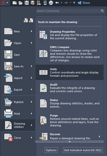
1) First Method
- Click on the Application menu present at the top left corner of the screen.
- A drop-down list will appear. Search for Drawing utilities in the list and click on it.
- A new drop-down list on the right side will emerge now.
- Select the units present in the list.
- The units dialog box will pop-up now.
2) Second Method
This step is one of the most universally followed step to enable the units in AutoCAD. The steps to be followed are listed below:
- Type UNITS or UN in the command line.
- Then press enter.
- Now the Drawing Units dialog box will pop-up in the workspace
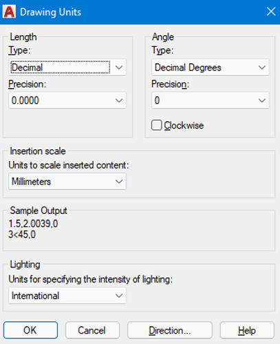
Units Dialog Box Explanation
Now, lets discuss in detail about the units dialog box.
(i) Length Type
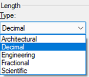
The various types of length in units are explained below:
- Architectural: In this type, the units are measured in feet and inches. It makes use of fractions to indicate partial inches. A single apostrophe (') denotes feet and a double apostrophe ('') denotes inches.
- Decimal: It is used to represent inch, meter, millimeter, or any required unit in decimal form.
- Engineering: It is similar to architectural units, as it uses feet and inches to represent the dimension of an object but in order to represent partial inches it uses decimal instead of fractions as in architectural units.
- Fractional: It is used to represent inch, meter, millimeter, or any required unit in the fractional form by making use of the fractions either a simple fraction or mixed fraction.
- Scientific: It is used to display larger values of dimensions with the help of exponents. They are generally used when the size of the component is really huge.
(ii) Angle Type
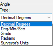
The various types of angles in units are explained below:
- Decimal: It is used to represent the angle value in decimal form.
- Deg/Min/Sec: It is used to represent the value of the angle in the form of degree, minute, and seconds. The degree is illustrated using (d), minute using a single apostrophe ('), and seconds using the double apostrophe ('').
- Grads and Radians: The Grads and Radians are nothing but mathematical functions. It is equated to angle as depicted below:
1 radian = 63.66 grad = 57.3 degree.
- Surveyor's Units: The surveyor's units are analogous to the grads and radians but it considers quadrants of a circle instead of considering it as a whole.
(iii) Angle Measure
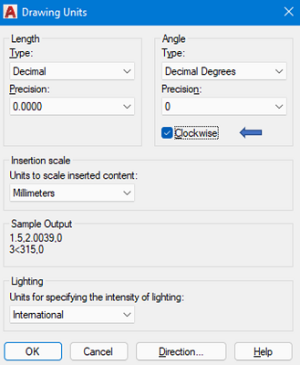
The angle measure is used to determine the direction in which the angle is to be measured either in a clockwise or counter-clockwise direction from the datum point. Generally, the angle measure direction is set to counter-clockwise direction but we can override it by selecting the clockwise option present in the Drawing Units dialog box.
(iv) Precision
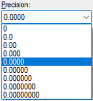
This command is used to determine the number of values that are required to be present after the decimal point. Based on the selected precision, the obtained value AutoCAD will be rounded off to provide the precision set by the user.
(v) Insertion Scale
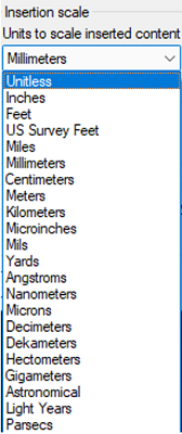
The insertion scale determines the type of measurement unit in which the drawing present in the workspace will be designated. There are a lot of units provided out of which the user selects the required type of unit needed for his drawing convenience.
(vi) Lighting
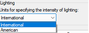
It is used for the purpose of specifying the intensity of lighting used in the workspace. It is generally classified as generic or photometric lights. By default, the generic option is set but this can be changed to photometric lights by either selecting international or American as per the requirement.
(vii) Direction
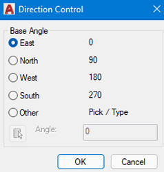
The direction control is used to determine the various faces within the workspace such as east, north, south and west. Normally, east is set as the base angle with counter-clockwise rotation but his can be changed by enabling the other option within the direction control dialog box.
Advertisement
Advertisement