Home »
Digital Electronics
Concept of Read-Only Memory (ROM) in Digital Electronics
Digital Electronics | Read-Only Memory (ROM): In this tutorial, we will learn about Read-Only Memory (ROM) in detail, what is the usage of ROM, their design procedure, and the different types of ROM.
By Saurabh Gupta Last updated : May 11, 2023
Read-Only Memory (ROM)
ROM is used only for performing Read operation. ROM is a non-volatile memory i.e., the information stored on the memory will not get erased even after power is turned off. That's why we have permanent programs (e.g.: Operating System programs) in ROM. Therefore, ROM is called as program memory.
Block Diagram of ROM
The block diagram of ROM can be drawn as:
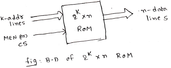
For ROM data lines are always output lines because it performs only Read operation.
Chip Select (CS) or Memory Enable (MEN) input is used to select a ROM IC. If CS=0, n-data lines will be in a high impedance state.
Types of Read-Only Memory (ROM)
1. Simple ROM and Masked ROM
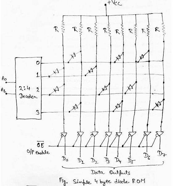
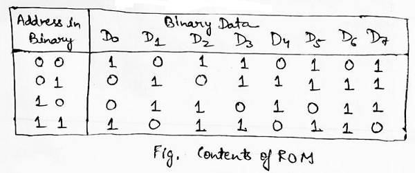
Earlier, simple ROMs were made using the diodes. A simple Diode ROM consists of only diodes and a decoder as shown in below fig. A 2:4 decoder is used to decode address lines A0 and A1 and it selects one of the four rows. Since the nature of the output of the decoder is active low, it places logic 0 on the selected row. When the diode connects the output data column to the selected row, then each data output line goes to logic 0. When the output-enable (OE) signal is lowDa, then data gets available on the output data lines.
In the present scenario, ROMs are built using MOS technology instead of using diodes. Some significant changes have been made like diodes and pull up resistors are replaced by MOS transistors. Just like in simple ROMs, A0 and A1 are decoded using 2:4 decoders, and the decoder selects one of the four rows making it logic 0. The not gate which is connected to the output of the decoder inverts the state of the selected row (i.e., from logic 0 to logic 1). Hence, when the gate of the MOS transistor is connected to the row select line, each output data line goes to logic 0. The MOS transistor is turned on when the gate of the MOS transistor is connected to the selected rows. This causes the corresponding column data line to go to logic 0.
The masked ROM has its storage locations written into (programmed) by the manufacturer according to the requirements of the customer.
Masked ROMs are used in Microprocessor-based toys, TV games, personal computers, etc.
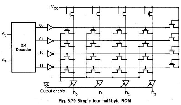
Image source: https://www.eeeguide.com/rom-memory/
2. Programmable Read-Only Memory (PROM) (or) Field PROM
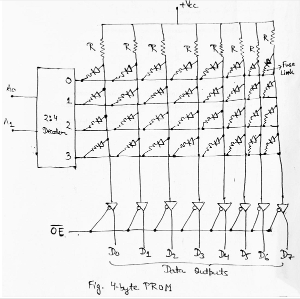
The PROM chip comes 'blank' and can be programmed only once by a user.
Above fig. shows 4-byte PROM. It has diodes in every bit position, therefore, the output is initially all 0's. Each diode inside the circuit has a fusible link connected in series with it. The fuse can be blown out by addressing the bit and applying proper current pulse at the corresponding output, hence, storing logic 1 at that bit position. The PROMs are one time programmable. Once programmed, the information stored is permanent.
3. Erasable Programmable Read-Only Memory (EPROM)
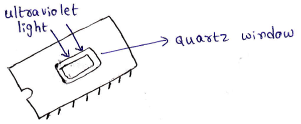
EPROMs use MOS circuitry. 0s and 1s are stored as a packet of charge inside a buried layer of the IC chip. EPROM chips can be erased and rewritten a no. of times. Stored data in the EPROM can be erased by exposing the chip to ultraviolet light through its quartz window for 15 to 20 minutes (before erasing the data we have to remove the IC from its socket.)
In EPROM, we cannot erase selective information, once something gets erased the entire information is lost. The chip can be reprogrammed. EPROM is ideally suitable for products and college laboratories since this chip can be reused many times. In EPROM, it is possible to program any location at any time, either individually, sequentially, or at random.
4. Electrically Erasable Programmable Read-Only Memory (EEPROM)
EEPROM is like EPROM except that the previously programmed connections can be erased with an electrical signal instead of ultraviolet light. The advantage of EEPROM over EPROM is that the device can be erased without removing it from the socket.
Advertisement
Advertisement