Home »
Digital Electronics
Realization of Boolean Expressions using Basic Logic Gates
In this tutorial, we will learn how to convert Boolean expression to logic circuit and convert logic diagrams into Boolean expressions with the examples.
By Saurabh Gupta Last updated : May 10, 2023
The main idea of making a Boolean Expression is to transform it into a logical circuit with the help of hardware devices. These logic circuits are made using logic gates. We need to choose that logical expression which is minimal and can be implemented easily and cheaply.
1. Converting Boolean Expression to Logic Circuit
The simplest way to convert a Boolean expression into a logical circuit is to follow the reverse approach in which we start from the output of the Boolean expression and reach towards the input.
Example 1
Realize the Boolean Expression BC + A + (A + C) using AOI logic
Solution
To realize this using the AOI logic gates, we will use the reverse approach.
Step 1:
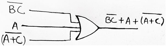
Our expression BC + A + (A+C) is the summation of three terms BC, A and, (A+C), thus a 3-input OR Gate must have been used to obtain the expression as given :0
Step 2:
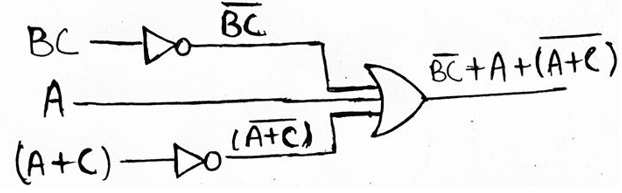
Now, BC and (A + C) both are inverted in nature, so they must have been inverted using a NOT Gate earlier. BC must have been obtained by inverting the input BC and (A + C) must have been obtained by inverting the input (A + C) both using the NOT Gate.
Step 3:
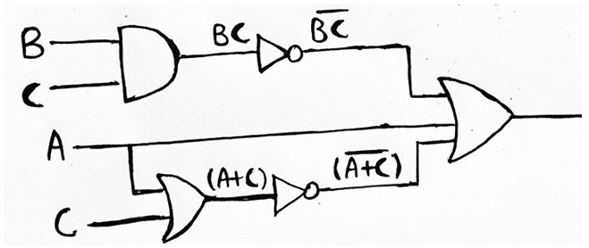
Moving further, in the reverse direction we see, BC must have been an output of 2-input AND Gate with inputs as B and C. Likewise, (A + C) must have been obtained as the output of 2-input OR gate with A and C as the inputs.
So, Final Logic Diagram for above given Boolean expression can be drawn as,
2. Converting Logic Diagrams into Boolean Expressions
The easiest way to obtain the Boolean Expression from any logic circuit is to follow the forward propagation approach. In this, we start from the input side and move ahead until the output is reached. While moving from the input side to the output side, we continue evaluating the output of intermediate logic gates.
Example 2
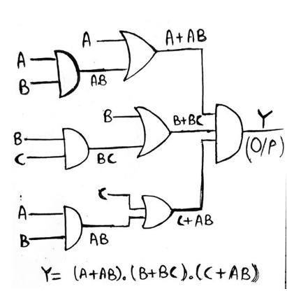
Find out the Boolean Expression for Logic Diagram given below and simplify the output in the minimal expression, also implement the simplified expression using the AOI logic
Solution
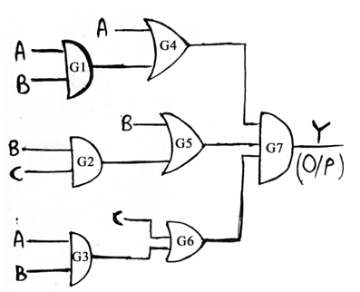
Following the forward propagation approach, we see that gate G1 is a 2-input AND Gate having inputs A and B. So, output of G1 will be AB. Similarly, G2 is an OR Gate, so output of G2 will be (B+C). Also, G3 is an AND Gate and its output will be AB.
Now, gate G4 is a 2-input OR Gate which has one of its inputs as A and the other one is the output of gate G1, thus the output of gate G4 will be (A + AB). Similarly, output for gate G5 and G6 will be (B + BC) and (C + AB) respectively. Now, gate G7 is a 3-input AND Gate, therefore output (Y) of G7 will be equal to (A+AB). (B+BC). (C+AB)
Since, we have Y = (A+AB). (B+BC). (C+AB), now we have to minimize it.
    Therefore, (A+AB). (B+BC). (C+AB)
    = A (1 + B). B (1 +C). (C+AB)
    = A. B. (C+AB)		[Since, 1+B =1 and 1+C =1]
    = AB (1 + C)
    = AB
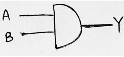
Therefore, Y=AB is the minimal expression. This can be implemented using a 2-input AND Gate having inputs A and B as:
Advertisement
Advertisement