Home »
Digital Electronics
Programmable Array Logic (PAL) in Digital Electronics
In this tutorial, we will learn about the programmable array logic (PAL) which belongs to the class of programmable logic devices (PLDs), its basic configuration, how they can be used to implement different combinational circuits, and the difference between PROM, PLA, and PAL.
By Saurabh Gupta Last updated : May 11, 2023
What is Programmable Array Logic (PAL)?
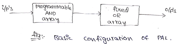
Programmable Array Logic (PAL) is a type of device which comes from the class of programmable logic devices (PLDs) and is used to implement combinational circuits. The basic configuration of a PAL consists of a programmable AND array and followed by a fixed OR gate. It differs from PLA in a manner, that PAL consists of an AND array followed by a fixed OR array whereas in case of PLA it has an AND array followed by a programmable OR gate. In PAL, since only AND array is programmable it is easier to use but it is not that flexible.
A schematic diagram of the basic configuration of PAL can be drawn as:
Programmable Array Logic (PAL) Examples
Example 1
Implement the following Boolean expression using PAL,
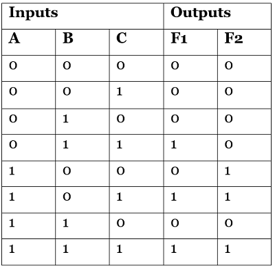
F1= ∑ m (3,5,7) and F2 = ∑ m (4,5,7).
Solution
Since, F1= ∑ m (3,5,7) and F2 = ∑ m (4,5,7). Truth table for Boolean functions F1 and F2 can be drawn as:
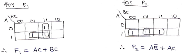
Now, for these Boolean functions, using the K-Map we can find the simplified Boolean expressions as:
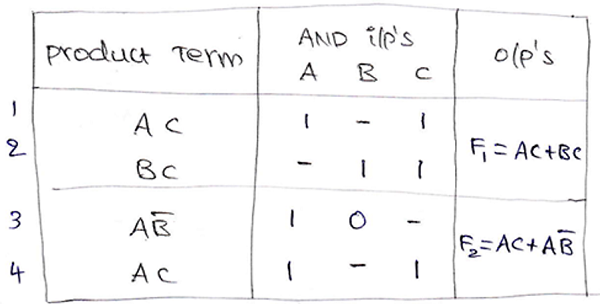
A PAL program table can be also drawn representing the terms in the Boolean expression as:
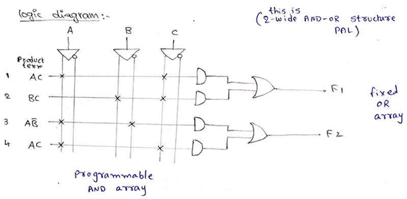
The logic diagram of the combinational circuit implemented using PAL can be drawn as:
Example 2
Implement the following Boolean expressions using a suitable PLA.
A (x,y,z) = ∑ m (1,2,4,6)
B (x,y,z) = ∑ m (0,1,6,7)
C (x,y,z) = ∑ m (2,6)
D (x,y,z) = ∑ m (1,2,3,5,7)
Solution
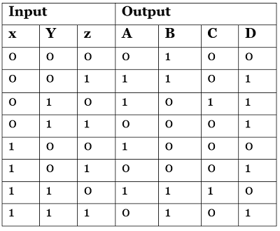
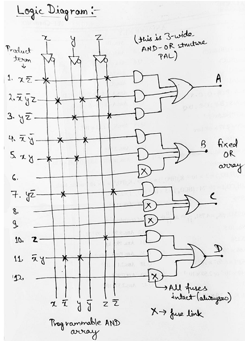
Truth table for Boolean functions A, B, C and D can be drawn as:
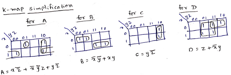
Solving K-Map to get the required Boolean expressions:
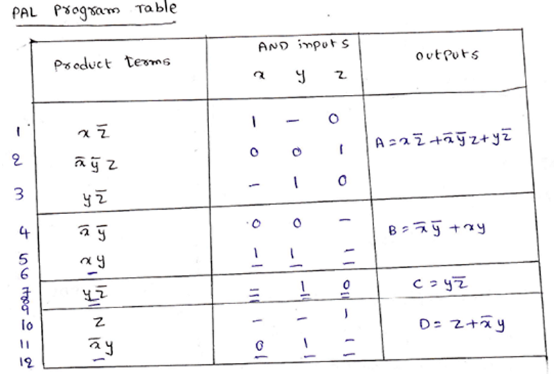
A PLA program table can be also drawn representing the terms in the Boolean expression as:
The logic diagram of the combinational circuit implemented using PLA can be drawn as:
Difference Between PROM, PLA, and PAL
The following are the key differences between PROM, PLA, and PAL:
| S.No. |
PROM |
PLA |
PAL |
| 1 |
It consists of a programmable OR array followed by a fixed AND array. |
It comprises both programmable OR array and AND array. |
It comprises a programmable AND array followed by a fixed OR array. |
| 2 |
It is cheaper and simpler to use. |
It is costliest amongst all and is also complex to use. |
It is cheaper and simpler to use. |
| 3 |
In this, all min-terms are decoded. |
AND array can be programmed to get the desired min-term. |
AND array can be programmed to get the desired min-term. |
| 3 |
If a Boolean function is in standard SOP form, then only it can be implemented using PROM. |
Any Boolean function needs not to be in standard SOP form, it can still be implemented using PLA. |
Any Boolean function needs not to be in standard SOP form, it can still be implemented using PLA. |
Advertisement
Advertisement