Home »
Digital Electronics
Construction of Code Converters
In this tutorial, we will learn about the Construction of Code Converters: Designing of Binary to Gray Code converter, Designing of Gray to Binary Code converter.
By Saurabh Gupta Last updated : May 11, 2023
In this article, we are going to read about how these code converters are designed and are implemented inside the system?
1. Designing of Binary to Gray Code converter
4-bit binary to gray code converter converts a 4-bit binary number to 4-bit gray code. Binary numbers are provided as input in the form of B3 B2 B1 B0 (MSB is the leftmost and LSB is the rightmost) and we get output in the form of Gray code as G3 G2 G1 G0 (MSB is the leftmost and LSB is the rightmost). Thus, the code converter is equivalent to four different logic circuits. One for each of the truth table. The next step is to derive simplified Boolean expressions for each truth table using the K-Map and then we can get the relation between input and output.
Let's create a conversion table that stores the inputs and their corresponding output for all possible cases of the 4-bit binary number.
| Input (Binary Code) |
Output (Gray Code) |
| B3 |
B2 |
B1 |
B0 |
G3 |
G2 |
G1 |
G0 |
| 0 | 0 | 0 | 0 | 0 | 0 | 0 | 0 |
| 0 | 0 | 0 | 1 | 0 | 0 | 0 | 1 |
| 0 | 0 | 1 | 0 | 0 | 0 | 1 | 1 |
| 0 | 0 | 1 | 1 | 0 | 0 | 1 | 0 |
| 0 | 1 | 0 | 0 | 0 | 1 | 1 | 0 |
| 0 | 1 | 0 | 1 | 0 | 1 | 1 | 1 |
| 0 | 1 | 1 | 0 | 0 | 1 | 0 | 1 |
| 0 | 1 | 1 | 1 | 0 | 1 | 0 | 0 |
| 1 | 0 | 0 | 0 | 1 | 1 | 0 | 0 |
| 1 | 0 | 0 | 1 | 1 | 1 | 0 | 1 |
| 1 | 0 | 1 | 0 | 1 | 1 | 1 | 1 |
| 1 | 0 | 1 | 1 | 1 | 1 | 1 | 0 |
| 1 | 1 | 0 | 0 | 1 | 0 | 1 | 0 |
| 1 | 1 | 0 | 1 | 1 | 0 | 1 | 1 |
| 1 | 1 | 1 | 0 | 1 | 0 | 0 | 1 |
| 1 | 1 | 1 | 1 | 1 | 0 | 0 | 0 |
From the truth table, we can observe that,
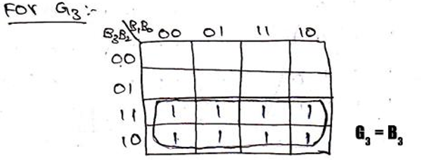
- The values in G4 are exactly the same as B4, thus we can get G4 = B4.
- The values in G3 is actually the output of XOR operation between the B4 and B3. Thus, G3 = B3 ⊕ B3.
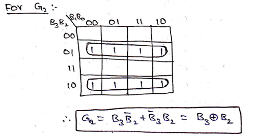
- The values in G2 is actually the output of XOR operation between the B3 and B2. Thus, G2 = B2 ⊕ B2.
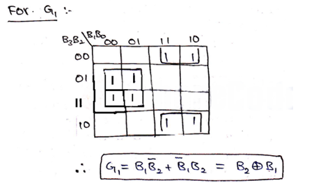
- The values in G1 is actually the output of XOR operation between the B2 and B1. Thus, G1 = B1 ⊕ B1.
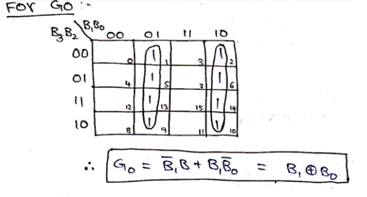
We can verify our observation by solving and obtaining Boolean expression from the K-Map for each of Gray code bits, we already know by convention 1s are the minterms for K-Maps, thus K-map can be solved as,
Thus, the logic circuit for 4-bit Binary to Gray code can be drawn as,
2. Designing of Gray to Binary Code converter
Gray code to Binary code converter can be designed in the same procedure as we have followed above. For all the possible cases of input (4-bit Gray code) G3 G2 G1 G0, we need to obtain simplified expressions for output (4-bit Binary code) B3 B2 B1 B0 by solving the K-Map. All possible inputs and outputs can be summarized in a truth table as,
| Gray Code (Input) |
Binary Code (Output) |
| G3 |
G2 |
G1 |
G0 |
B3 |
B2 |
B1 |
B0 |
| 0 | 0 | 0 | 0 | 0 | 0 | 0 | 0 |
| 0 | 0 | 0 | 1 | 0 | 0 | 0 | 1 |
| 0 | 0 | 1 | 0 | 0 | 0 | 1 | 1 |
| 0 | 0 | 1 | 1 | 0 | 0 | 1 | 0 |
| 0 | 1 | 0 | 0 | 0 | 1 | 1 | 1 |
| 0 | 1 | 0 | 1 | 0 | 1 | 1 | 0 |
| 0 | 1 | 1 | 0 | 0 | 1 | 0 | 0 |
| 0 | 1 | 1 | 1 | 0 | 1 | 0 | 1 |
| 1 | 0 | 0 | 0 | 1 | 1 | 1 | 1 |
| 1 | 0 | 0 | 1 | 1 | 1 | 1 | 0 |
| 1 | 0 | 1 | 0 | 1 | 1 | 0 | 0 |
| 1 | 0 | 1 | 1 | 1 | 1 | 0 | 1 |
| 1 | 1 | 0 | 0 | 1 | 0 | 0 | 0 |
| 1 | 1 | 0 | 1 | 1 | 0 | 0 | 1 |
| 1 | 1 | 1 | 0 | 1 | 0 | 1 | 1 |
| 1 | 1 | 1 | 1 | 1 | 0 | 1 | 0 |
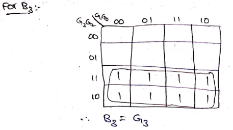
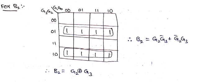
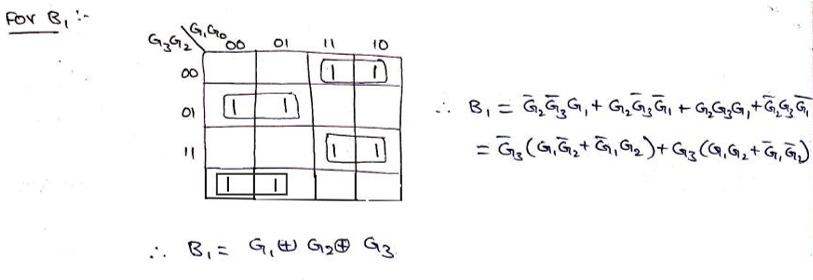
Solving K-Map to get the required Boolean expressions,
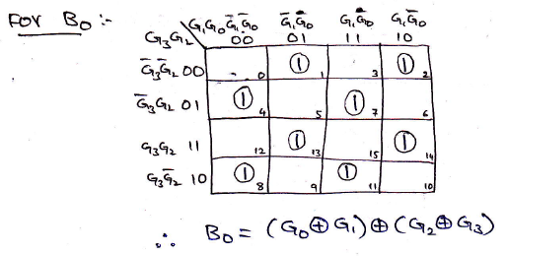
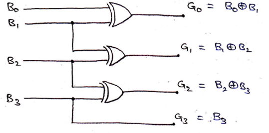
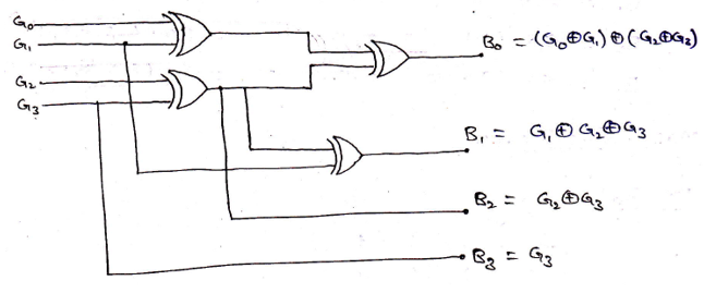
Logic Diagram for Gray to Binary converter can be drawn as,
Advertisement
Advertisement