Home »
Digital Electronics
Logic Gates: Definition, Types, Uses, Symbols, Truth Tables
Digital Electronics | Logic Gates: In this tutorial, we will learn about the logic gates, types of logic gates, their uses, symbols, and truth tables with the help of examples.
By Saurabh Gupta Last updated : May 10, 2023
What are Logic Gates?
Logic Gates are the fundamental building blocks of a digital system. The name Logic Gates has been derived from the fact that the device should be able to make decisions on its own. It should be able to distinguish different output levels, for example, one output level is produced when some level of input is present and other output level is produced when another set of input is provided.
Input and Output of logic gates occur in only two states either ON/High/True or OFF/Low/False. We simply represent these in numerical form as 1 and 0 respectively.
A Truth Table contains all possible combinations of inputs and their possible outputs. It shows how the logic circuit's output responds to various combinations of logic levels at the inputs.
Types of Logic Gates
There are five types of gates of which three are the basic gates (AND, OR, NOR gates) and two more are derived from the basic gates (XOR, XNOR gates). Let's discuss them in detail.
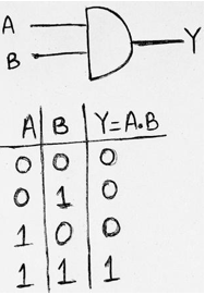
1. AND Gate
An AND Gate may have two or more inputs. The output of AND Gate will be 1 when all of its inputs are in state 1. The output will be in 0 states if even any one of its inputs is in state 0. Logic operation of AND Gate is given as Y= A.B.
Symbol and Truth table for AND Gate:
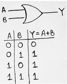
2. OR Gate
An OR Gate may also have two or more inputs. The output of OR Gate will be 1 when any of its inputs are in state 1. The output will be in 0 state, if all of its inputs are in state 0. Logic operation of OR Gate is given as Y = A+B.
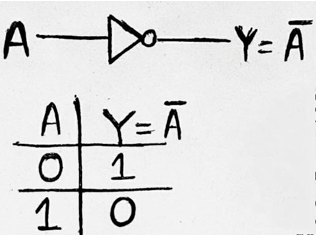
3. NOT Gate
A NOT Gate is used for complementing the input provided. If the input will be high then output will be low and vice-versa. Logic operation of NOT Gate is given as: Y=A'/A (provided A is the input) which is read as A compliment.
Symbol and Truth table for NOT Gate:
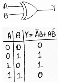
4. Exclusive-Or Gate/XOR Gate
An XOR Gate has two inputs. The output of XOR Gate will be 1 when and only one of its inputs is provided high state (1). The output will be in 0 state, if both of its inputs are in logic state 0 or logic state 1. Logic operation of XOR Gate is given as: Y= AB + AB = A⊕B.
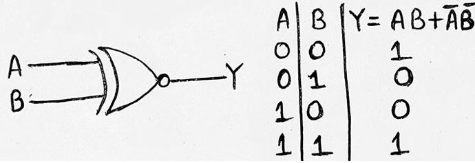
5. Exclusive-NOR Gate/XNOR Gate
An XNOR Gate has two inputs. The output of XNOR Gate will be 1 when and when both of its inputs are provided either low state (0) or high state (1). The output will be in 0 state, when one of its inputs is in logic state 0 and another in logic state 1. Logic operation of XNOR Gate is given as Y= AB + AB = A⨀B.
Advertisement
Advertisement