Home »
Digital Electronics
Programmable Logic Array (PLA) in Digital Electronics
In this tutorial, we will learn about the programmable logic array (PLA) which belongs to the class of programmable logic devices (PLDs), its basic configuration, how they can be used to implement different combinational circuits.
By Saurabh Gupta Last updated : May 11, 2023
What is Programmable Logic Array (PLA)?
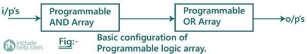
Programmable Logic Array (PLA) is a type of device which comes from the class of programmable logic devices (PLDs) and is used to implement combinational circuits. The basic configuration of a PLA consists of a programmable AND gate followed by a programmable OR gate. Although PLA contains the word programmable inside it, it does not have to be programmed explicitly using any programming languages like C, C++, Java, Python, etc.
A schematic diagram of the basic configuration of PLAs can be drawn as:
Programmable Logic Array (PLA) Examples
Example 1
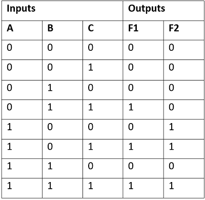
A combinational circuit is defined by the function F1= ∑ m (3,5,7), F2 = ∑ m (4,5,7). Implement the circuit using a PLA which consists of 3 inputs (A, B and C), 3 product terms and two outputs.
Solution
Since, F1= ∑ m (3,5,7) and F2 = ∑ m (4,5,7). Truth table for Boolean functions F1 and F2 can be drawn as:
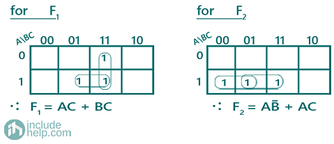
Now, for these Boolean functions, using the K-Map we can find the simplified Boolean expressions as:
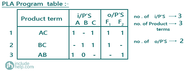
A PLA program table can be also drawn representing the terms in the Boolean expression as:
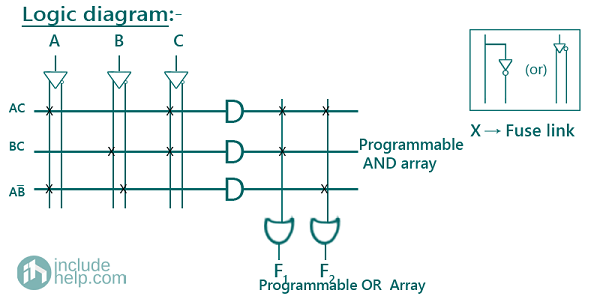
The logic diagram of the combinational circuit implemented using PLA can be drawn as:
Example 1
Design a BCD to Excess-3 code converter and implement it using a suitable PLA.
Solution
Truth table for BCD to Excess-3 converter can be drawn as:
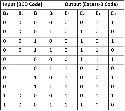
Note: Since, BCD numbers are from 0-9, hence other combinations representing (10-15) are considered as don’t cares while solving the K-Map.
Boolean Expressions for all the outputs can be written as:
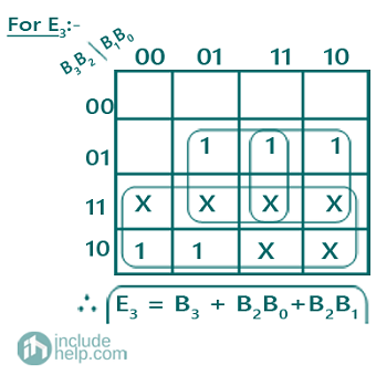
E3 = ∑m (5,6,7,8,9) + ∑d (10,11,12,13,14,15)
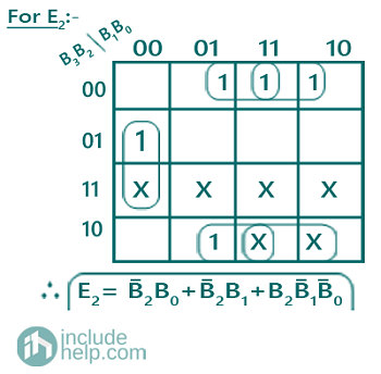
E2 = ∑m (1,2,3,4,9) + ∑d (10,11,12,13,14,15)
E1 = ∑m (0,3,4,7,8) + ∑d (10,11,12,13,14,15)
E0 = ∑m (0,2,4,6,8) + ∑d (10,11,12,13,14,15)
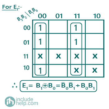
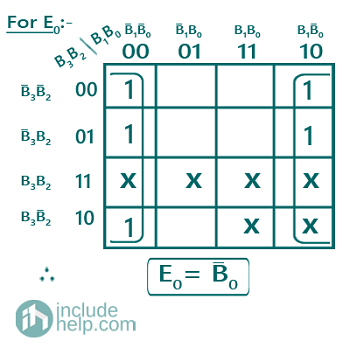
Solving K-Map to get the required Boolean expressions:
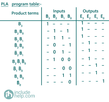
A PLA program table can be also drawn representing the terms in the Boolean expression as:
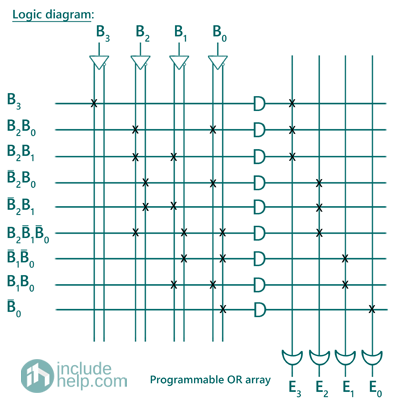
The logic diagram of the combinational circuit implemented using PLA can be drawn as:
Advertisement
Advertisement