Home »
Digital Electronics
How to Design Asynchronous Counters?
In this tutorial, we will learn the procedure of designing asynchronous counters, their working, and their output waveforms.
By Saurabh Gupta Last updated : May 11, 2023
1. Design 3-bit Asynchronous/Ripple Up Counter
As we know that about the counters, an up-counter counts in the upward direction from 0, 1, 2, ..., N.
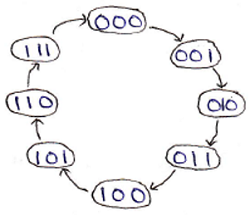
We can represent binary numbers using 3-bits from 0 to 7, i.e., we can draw a state diagram which represents the states, 3-bit up counter undergoes during its working. It is shown as:
A 3-bit ripple counter requires 3 flip-flops to store 3 bits. As it is an asynchronous counter, an external clock is connected to the very first flip-flop only, and then the output of the preceding flip-flop acts as the clock input for the next flip-flops in the circuit. A logic circuit of 3-bit ripple up counter made using JK flip-flop is shown below figure:
Design 3-bit ripple up counter using negative edge-triggered flip-flop
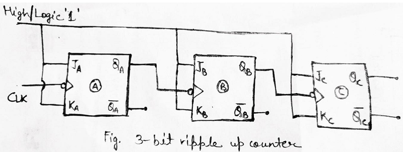
The above circuit is made using negative edge-triggered flip- flops means they will be triggered when the negative edge of the clock arrives. The Counter produces the output from QC, QB, and QA in which QC is the MSB, and QA is the LSB. An output waveform can be drawn to understand its working more clearly which can be shown as:
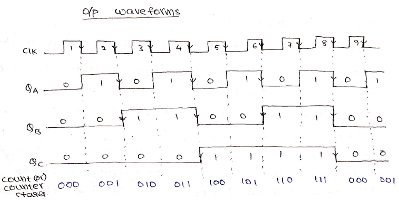
Also, from the above output waveform, we can notice that the time period for each output gets increases successively i.e., originally suppose we supplied a clock pulse with time period T, then in output QA time period increases to T/2, in output QB time period increases to T/4 and lastly in output, QC time period increases to T/8. Since we have an inverse relationship between time period and frequency, the frequency decreases as the time period increases. Originally, the frequency was f then after passing through multiple cascaded flip-flops frequency decreases as f/2, f/4, and f/8 respectively. Using this we can make a conclusion that a ripple counter can also be used as a frequency divider.
Design 3-bit ripple up counter using positive edge-triggered flip-flop
For designing a 3-bit ripple up counter using a positive edge-triggered flip-flop, we need to connect all Q' outputs to the clock inputs of the next flip-flop. The logic circuit diagram, in this case, can be drawn as:
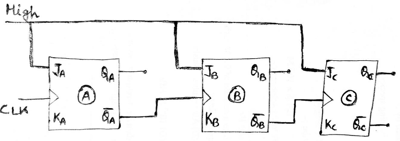
Fig. 3-bit ripple up-counter made using '+ve edge-triggered JK flip-flop'
Note: A general formula can be derived using the above conclusion, an n-bit counter decreases original frequency by a factor of 2n. For Example: In the 3-bit ripple counter, frequency got reduced by 23 = 8 factors i.e., original frequency f was reduced to f/8.
strong>Mod Counters: The number of states through which the counter passes before returning to the starting state is called the modulus of the counter OR the mod of a counter is the total number of states it sequences through in each complete cycle.
For E.g.: Since a 3-bit counter has a total of 8 states, it is called a Mod-8 or Modulus-8, or Modulo-8 counter.
2. Design Asynchronous Mod-10 Counter/ Decade Counter/ BCD Counter
A mod-10 ripple counter counts from 0 to 9 and goes back to 0 states in the 10th clock pulse. The state diagram for mod-10 counter can be drawn as:
State diagram:

A table can be drawn to show the counting sequence for this decade counter. It is clear from this table that the counter should reset itself when Q3 Q2 Q1 Q0 becomes 1 0 1 0 i.e., a low pulse should be generated when Q3 Q1 becomes 1 1. So Q3 and Q1 outputs are applied to a NAND gate, which will make output low when Q3 Q1 = 1 1.
This low pulse should be applied to CLR terminals of all the flip-flops.
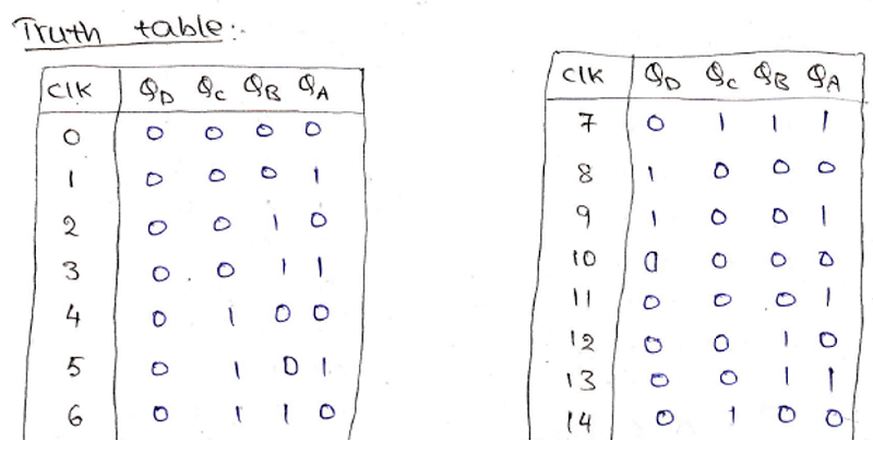
The logic circuit diagram of the ripple decade counter can be drawn using negative-edge triggered JK flip-flop as:
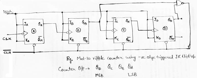
At the trailing edge of the 10th pulse, the counter temporarily becomes 1010 state, but immediately resets to 0000, since the output of the NAND gate is connected to reset or CLR inputs of flip-flops counter enter into 0000 state at 1010 state.
Advertisement
Advertisement