Home »
Digital Electronics
Examples of Designing of Synchronous Mod-N Counters
Synchronous Mod-N Counters: Here, we have some examples for designing synchronous mod-N counters in Digital Electronics.
By Saurabh Gupta Last updated : May 11, 2023
Example 1: Design a mod – 5 synchronous counters using JK flip-flop.
A mod-5 counter counts from 0 to 4. Thus, following the steps given in article - designing of synchronous counter, a mod-5 counter can be designed as:
Step 1: The number of flip-flops required to design a mod-5 counter can be calculated using the formula: 2n >= N, where n is equal to no. of flip-flop and N is the mod number. In this case, the possible value on n which satisfies the above equation is 3. Hence, the required number of flip-flops is 3.
Step 2: The type of flip-flop required to design the counter is JK flip-flop.
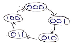
Step 3: We can draw the state diagram for mod-5 counter describing the state flow in current and next state as:
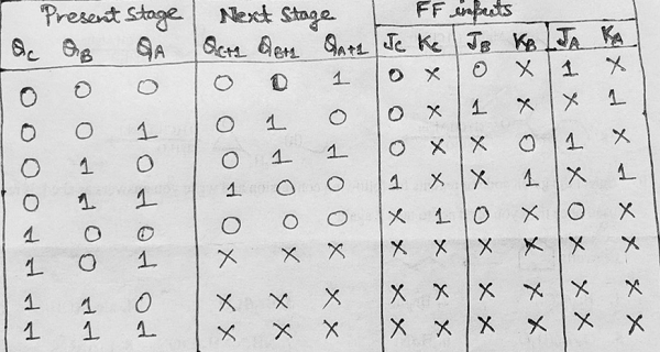
Step 4: Using the excitation table of JK flip-flop, we need to obtain the flip-flop inputs for each state that we obtained in the third step and now we will enter it into a table as:
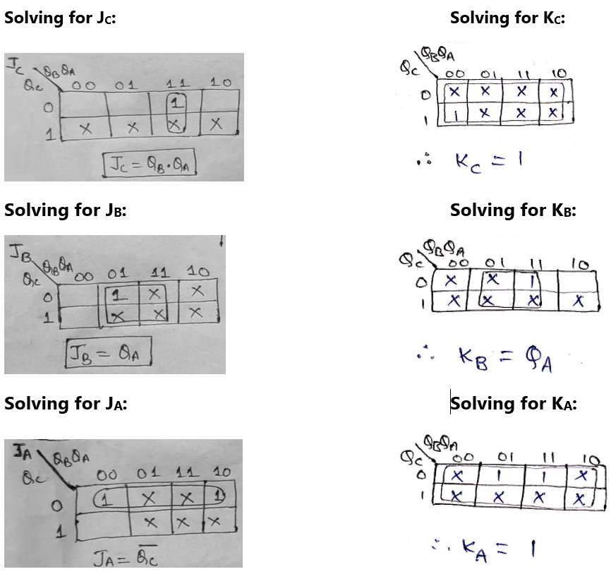
Step 5: Making K-Map for each input combination and simplifying it to get the minimized Boolean expression.
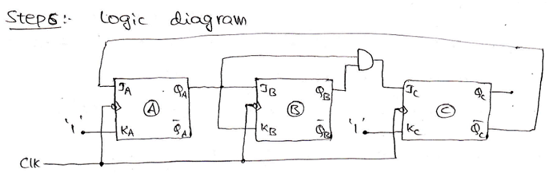
Step 6: Using the Boolean expressions obtained in step 5, now we will draw the required counter circuit which can be shown as:
Example 2: Design a mod - 10 synchronous counter/ Decade counter/ BCD counter using T flip-flop
A mod-10 counter counts from 0 to 9. Thus, following the steps given in the article - designing of synchronous counter, a mod-10 counter can be designed as:
Step 1: The number of flip-flops required to design a mod-10 counter can be calculated using the formula: 2n >= N, where n is equal to no. of flip-flop and N is the mod number. In this case, the possible value on n which satisfies the above equation is 4. Hence, the required number of flip-flops is 4.
Step 2: The type of flip-flop required to design the counter is T flip-flop.
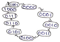
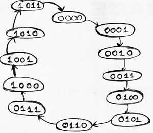
Step 3: We can draw the state diagram for mod-10 counter describing the state flow in current and next state as:
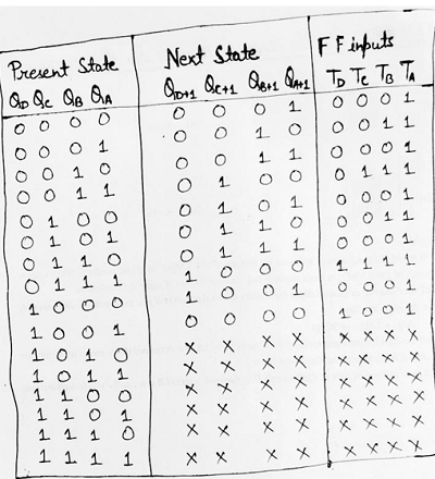
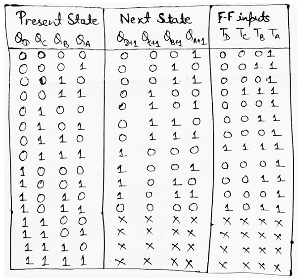
Step 4: Using the excitation table of T flip-flop, we need to obtain the flip-flop inputs for each state that we obtained in the third step and now we will enter it into a table as:
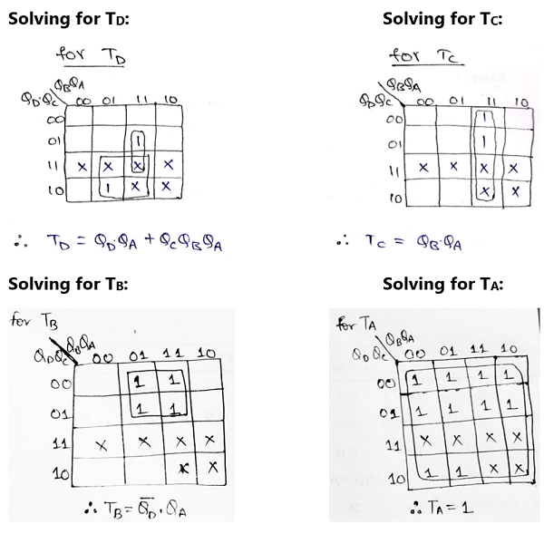
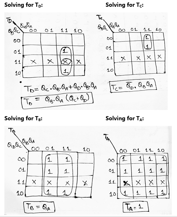
Step 5: Making K-Map for each input combination and simplifying it to get the minimized Boolean expression.
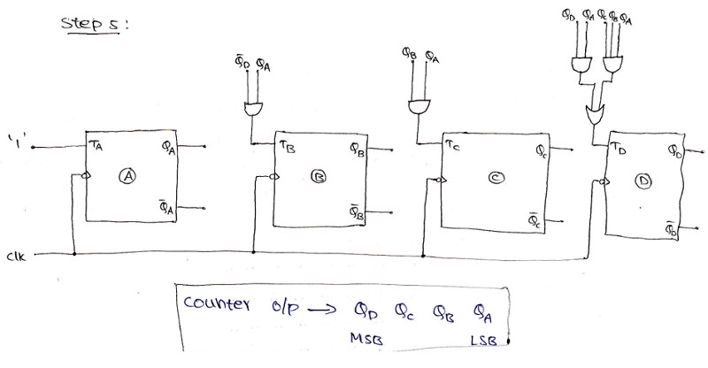
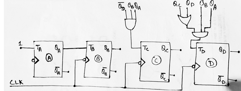
Step 6: Using the Boolean expressions obtained in step 5, now we will draw the required counter circuit which can be shown as:
Example 3: Design a mod -12 synchronous up counter using T flip-flop
A mod-12 up-counter counts from 0 to 11. As already seen in previous examples, we should follow similar steps and hence a mod-12 counter can be designed as:
Step 1: The number of flip-flops required to design a mod-12 counter can be calculated using the formula: 2n >= N, where n is equal to no. of flip-flop and N is the mod number. In this case, the possible value on n which satisfies the above equation is 4. Hence, the required number of flip-flops is 4.
Step 2: The type of flip-flop required to design the counter is T flip-flop.
Step 3: We can draw the state diagram for mod-12 counter describing the state flow in current and next state as:
Step 4: Using the excitation table of T flip-flop, we need to obtain the flip-flop inputs for each state that we obtained in third step and now we will enter it into a table as:
Step 5: Making K-Map for each input combination and simplifying it to get the minimized Boolean expression.
Step 6: Using the Boolean expressions obtained in step 5, now we will draw the required counter circuit which can be shown as:
Advertisement
Advertisement