Home »
Digital Electronics
N-bit Parallel Adders (4-bit Binary Adder and Subtractor)
In this tutorial, we will learn about the N-bit Parallel Adders (4-bit Binary adders and Subtractors) in Digital Electronics.
By Saurabh Gupta Last updated : May 11, 2023
Till now, we have already read (in the previous articles) about designing and uses of the basic form of adders and subtractors such as Half Adder, Full Adder, Half Subtractor, and Full Subtractor. In this article, we are going to learn about the more advanced concept of adders and subtractors and their design and uses using block diagrams and logic circuit diagrams.
Parallel Binary Adder
As, we already know, a full adder was used to add two 1-bit binary numbers and the additional carry bit (Cin). But, to add two n-bit binary numbers, we will require n-number of full adders. The addition of LSB bits can be done by using any of half-adder or a full-adder with Cin terminal grounded, but in practical parallel adders, we use a full-adder at the least significant stage also to facilitate cascading. The carry-out of each full-adder is also connected to the carry-in of the next full-adder in the higher-order. A parallel adder is used to add two numbers in parallel form and to produce the sum bits as parallel outputs. In two numbers, one is addend and the other is augend and both are added parallelly to get the sum.
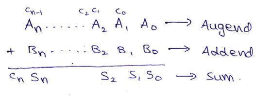
Two n+1-bit binary number A and B of the form,
A:  An An-1 An-2 ... A3 A2 A1 A0 (Augend)
B:  Bn Bn-1 Bn-2 ... B3 B2 B1 B0 (Addend)
can be added as,
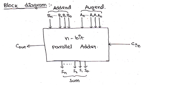
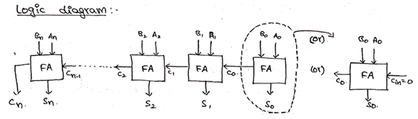
Block diagram and Logic circuit diagram of a Parallel Binary adder can be given as,
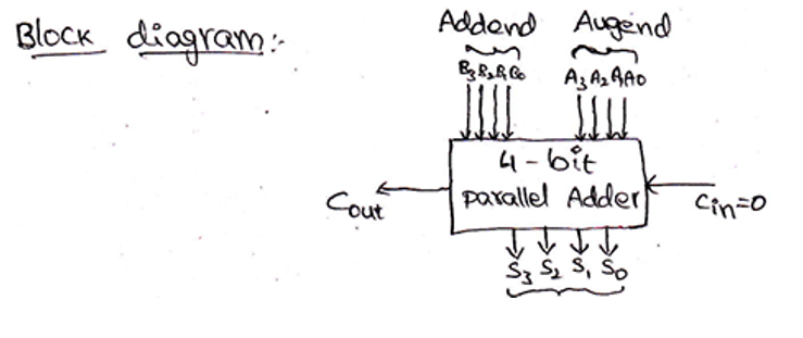
4-bit Binary Adder
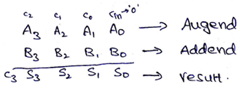
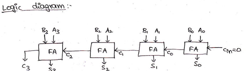
From the above-provided logic, we need 4 full adders connected together to add 4-bit binary numbers. For 4-bit binary numbers A and B of the form,
A: A3 A2 A1 A0 and B: B3 B2 B1 B0, its sum can be obtained as,
Block diagram and Logic circuit diagram of a 4-bit Binary adder can be given as,
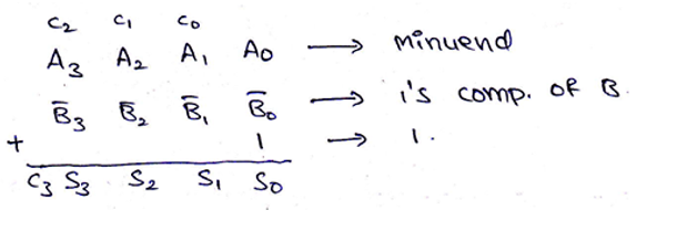
4-Bit Binary Subtractor
We already know that two numbers A (Minuend) and B (Subtrahend) can be subtracted using 2s complement method, where,
A – B   = A + 2s complement of B
        = A + 1s complement of B + 1
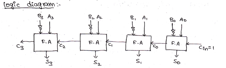
Thus, 4-bit binary numbers A and B can subtract as,
And the logic circuit for the same can be drawn as,
Parallel Adder/Subtractor using a single circuit can be also designed using a Mod bit (M), where mod bit M decides whether the circuit will act as an adder or a subtractor. When M=0, then the circuit acts as an adder and when M=1, then the circuit acts as a subtractor. The circuit for the same can be drawn as,
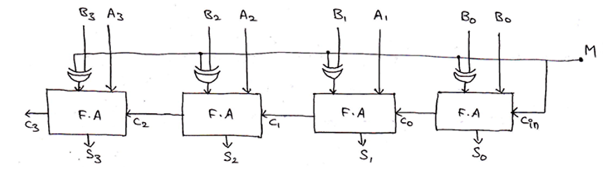
When M=0,
output  = A3 A2 A1 A0 + B3 B2 B1 B0 + Cin          [Since, A⊕0 = A]
        = A3 A2 A1 A0 + B3 B2 B1 B0 + 0
        = A + B
Thus, circuit acts as a 4-bit binary adder.
When M=1,
output  = A3 A2 A1 A0 + B3 B2 B1 B0 + Cin
        = A3 A2 A1 A0 + B3 B2 B1 B0 + 1
        = A + B + 1
        = A – B
Thus, circuit acts as a 4-bit binary subtractor
Advertisement
Advertisement