Home »
Software Engineering
Component Diagram in Unified Modeling Language (UML)
In this tutorial, we will learn about the component diagram in unified modeling language (UML), its various parts, and usage.
By Monika Sharma Last updated : April 05, 2023
What is a Component Diagram?
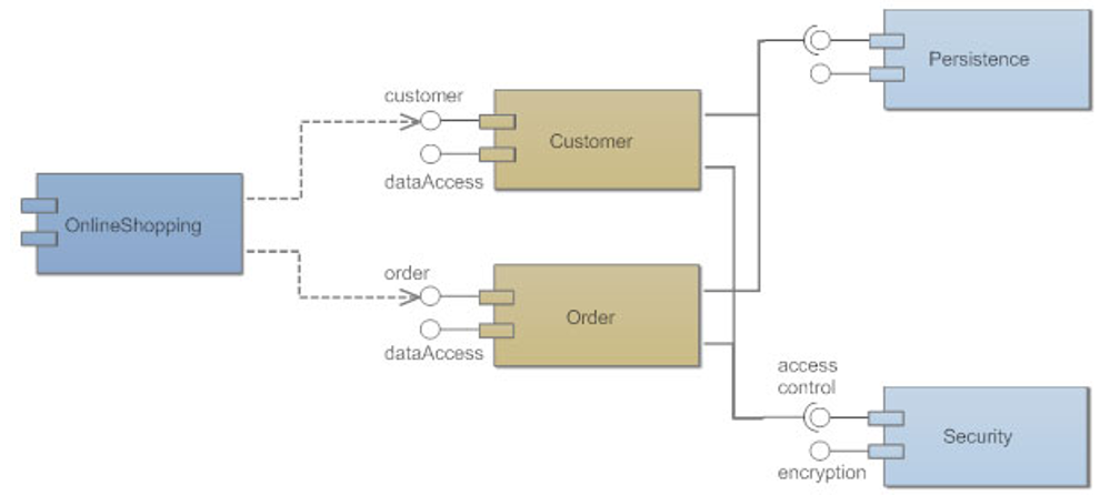
A Component Diagram breaks down the real system under development into different heights of working. Every component is reactive for the main aim in the entire system and only reacts with other particular elements on a need to know basis. The interfaces on the right are defined as required interfaces, which shows the services the component wants to carry out its duty.
The Concept of Component Diagram
A component represents a modular part of a system of the diagram that encapsulates its contents and tells whose manifestation is replaceable the states within its environment of the world. In the UML diagram, a component is drawn as four sides as breadth and length known as a rectangle with optional compartments stacked straightly as vertical. A high-level, abstracted view of a component in UML 2 can be modeled as:
- A rectangle with the component's name
- A rectangle with the component icon
- A rectangle with the stereotype text and/or icon
Take stock of everything or anything needed or wanted to implement or run the planned system. For example, for a simple e-commerce system, we will need components or parts of the component that describe products, orders, objective, server account, and customer accounts.
Form a visual or imaginary for each of the components of the system.
Defines the organization and relationships between components having the parts using interfaces, ports, and dependencies together to form components.
Parts of Component Diagram
The different parts of component diagram are:
1) Component
A component is a logical unit block of the system of the objects, a little large flow abstraction than classes. It is shown as a length and breadth rectangle with a smaller rectangle in the upside of right corner or site with tabs or the word written or shows above the name of the component to help differentiate it from a class.
2) Interface
An interface (small circle or semi-circle on a stick) differentiate a group of operations required or something provided by components. A full circle represents an interface provided by the component and uses for the interface between the two systems. A semi-circle represents a required interface, like a person's input as the objects of the system.
3) Dependencies
Draw dependencies among al the components using dashed arrows.
4) Port
Ports are represented using four equal sites as square along the edge of the system or a component. A port is used to input the system object into it. A port is often used to help to expose required and provided and interfaces of a component of the system.
Use of Component Diagram
The component diagram is used for the various purposes:
- Design the components of a system.
- Program the database schema.
- Make the executables of an application.
- Draw the system's source code.
Advertisement
Advertisement