Home »
Software Engineering
Sequence Diagram in Unified Modeling Language (UML)
In this tutorial, we will learn about the sequence diagram in unified modeling language (UML).
By Monika Sharma Last updated : April 05, 2023
What is Sequence Diagram?
Sequence Diagram is a "Connection Diagram" that represents a single structure or storyline executing in a system. It is the second most used UML diagram behind the class diagram. Sequence Diagram shows what message is to be sent and when.
A sequence diagram is a good way to visualize and ratify various runtime framework.
Basic Sequence Diagram Notation
The basic sequence diagram notation are:
1) Lifeline
Lifelines are vertical dotted lines that indicate the object's activity over time. Lifeline is a named element that represents an individual participant in the connection. While parts and structural properties may have multiplicity, lifelines represent only one interconnected entity.
2) Messages
Messages are nothing but the arrows that represent calls between objects. Half-arrowed lines are used to represent asynchronous messages. Asynchronous messages are sent from an object that will not wait for a reply from the receiver before continuing its tasks.
3) Execution Occurrence
Execution boxes present the time an object needs to complete a task. When an object is busy executing a process or waiting for a reply message, use a thin gray rectangle placed vertically on its lifeline.
4) Interaction Fragment
It is the named element that represents the most general interaction segment. Example of Interaction Fragment:
- Occurrence
- Execution
- Interaction use
Types of Messages in Sequence Diagram
The different types of messages are:
1) Synchronous Message
It requires a response before the interaction can proceed. It's usually drawn using a line with a solid arrowhead pointing from one object to another.
2) Asynchronous Message
It does not require a response before the interaction can proceed. It is usually drawn using an arrow.
3) Reply Message
It is drawn by the dotted arrow moving backward to the original message.
4) Self Message
A message sent to itself and it is represented by the U shaped arrow.
5) Found Message
A message sent from an unknown beneficiary, shown by an arrow from an endpoint to a lifeline.
6) Lost Message
A message sent to an unknown beneficiary. It's shown by an arrow going from a lifeline to an endpoint, a filled circle or a cross(x).
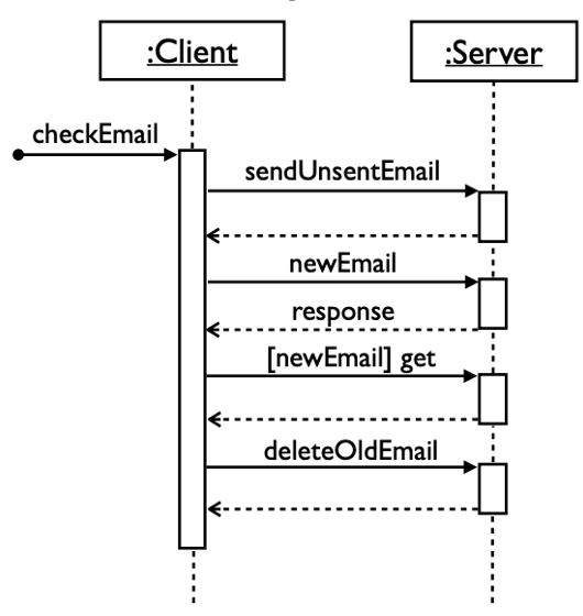
Simple E2E Diagram
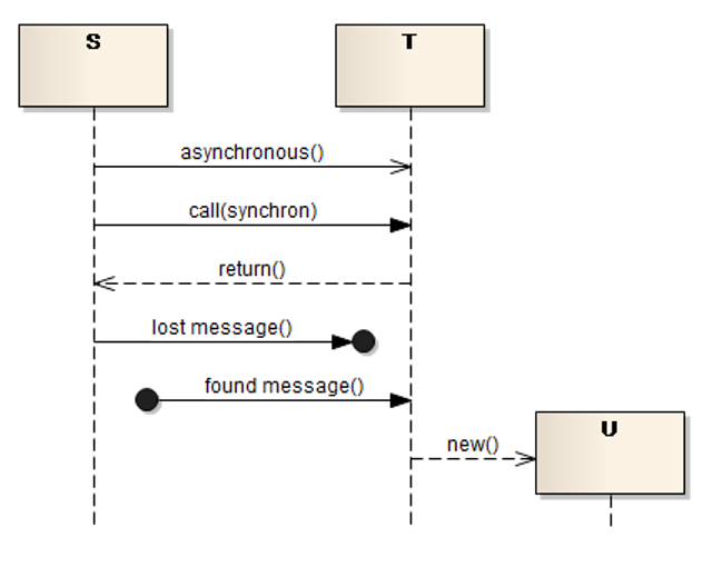
Image Reference: https://www.sparxsystems.eu/resources/project-development-with-uml-and-ea/interaction-diagram/
Advertisement
Advertisement