Home »
Software Engineering
Deployment Diagram in Unified Modeling Language (UML)
In this tutorial, we will learn about the deployment diagram in unified modeling language (UML), its notations, and examples.
By Monika Sharma Last updated : April 05, 2023
What is Deployment Diagram in UML?
A deployment diagram is a UML diagram type of the system that represents the execution architecture of the components of a system of the objects, including nodes or modes such as hardware or software execution environments or worlds, and the middleware connecting them. Diagram types mostly outline the logical components of a system. Deployment diagrams are typically or difficultly used to visualize or imagine the physical hardware and software of a system of the component. Using it you can understand how the system of the diagram will be physically deployed on the hardware.
Deployment diagrams help design the hardware topology of a system of component compared to other UML diagram types from the others which mostly outline the logical components of a system in the diagram for the use of deploy of the component.
Deployment Diagram Notations
The various notations of the deployment diagram are:
1) Nodes
A node, represented as 8 faces as the cube, is a physical entity that executes one or more components, subsystems or executables of the system. A node could be a hardware or software element of the system.
2) Artifact
Artifacts are concrete elements that are caused or problemed by a development process. Examples of artifacts are libraries, archives, configuration files, executable files, deploy files, etc.
3) Communication Association
This is represented by a solid line between two nodes. It shows the path of communication between nodes.
4) Devices
A device is a node that is used to represent a physical computational resource in a system. An example of a device is an application server.
5) Deployment Specifications
Deployment specifications is a configuration file, such as a text file or an XML document. It describes how an artifact is deployed on a node.
Use of Deployment Diagram
- What existing systems will the newly added system of the component want to interact or integrate with?
- How robust does the system need to be redundant for deploy?
- What and who will connect to or interact with the system of the component, and how will they do it with it and the diagram?
- What middleware, including the operating system and communications approaches and protocols, will system use this with altogether or not?
- What hardware and software will users directly interact with (PCs, network computers, browsers, etc.) for deployment?
- How will you monitor the system once deployed for the diagram?
- How secure does the system need to be (needs a firewall, physically secure hardware, etc.) with deploy?
Deployment Diagram Examples
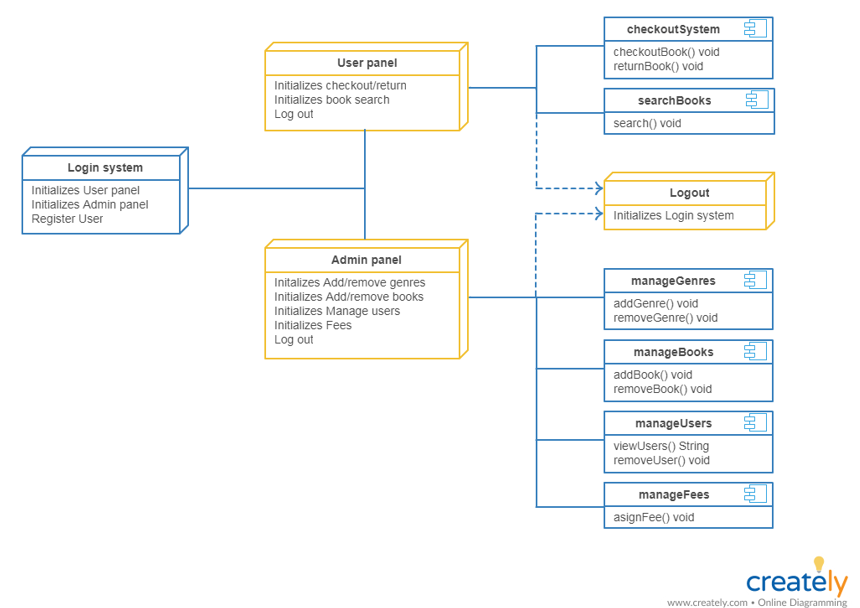
1) Deployment Diagram for Online Shopping System
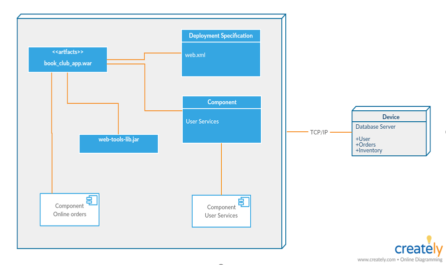
2) Deployment Diagram for Library Management System
Images source: http://creately.com/creately-start?tempID=jmk6au3v1
Advertisement
Advertisement