Home »
Software Engineering
Activity Diagram in Unified Modeling Language (UML)
In this tutorial, we will learn about the activity diagram in unified modeling language (UML).
By Monika Sharma Last updated : April 05, 2023
Activity Diagram in UML
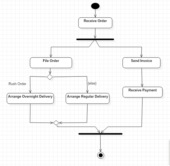
The Activity diagram in the software design models is used to represent the flow of control among the different activities of the software. In the activity diagram, we represent different actions through activities. These activities take some input from some other activity of the system or through the input and output units and produce some signal outputs that control the workflow of the other activities.
The activities in the activity diagram can be defined as states. Each of these states performs some internal action that is responsible for performing the required task. Apart from this, each activity also performs some external activity. This external activity can either be responsible for triggering or handling some other activities or can be used for directly producing the required output. Each activity can produce one or more external transitions. If there is direct workflow form one activity to another activity without any specific conditional case, then the activity produces only one external transition. If more than one external transition is produced by the activity, then these transitions are handled through the conditional statements (like if-else).
Characteristics of Activity Diagram
- The control flow in every software has to start from some starting point and end at some termination point. In the activity diagram, the starting point is represented through a filled circle and the termination point through a filled circle with a double boundary. Every activity diagram must contain these symbols.
- The activity diagram can also be divided into different categories using the swim lanes. Each lane represents a single category and all the activities belonging to this category are represented in this lane.
- The conditional statements can be represented in the activity diagram by placing a diamond symbol from the line representing the external transition and then splitting this line according to desired conditions. The condition that each of these divisions follows can be mentioned on top or beside the line.
- The diamond symbol is also used for conjugating the external transitions from various activities. Most of the time, this type of situation occurs when the activity model proceeds towards the termination stage.
Features of Activity Diagram
- This model is prepared in the early stages of software development, i.e. in the analysis and design phase.
- Internal control flow can be well represented through this model.
- Complex processing activities that involve many elements and components can easily be represented understandably through this model.
Advertisement
Advertisement